
Specification Sheet
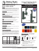

halseytaylor.com
HALSEY TAYLOR, 2222 Camden Court, Oak Brook, IL 60523
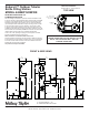
FINISHED FLOOR
4"
102mm
27"
686mm
19"
483mm
2 7/8"
73mm
WATER INLET
DRAIN LINE
64"
1626mm
8"
203mm
34 11/16"
881mm
ORIFICE
HEIGHT
44"
1118mm
14 9/16"
371mm
3"
76mm
O
10"
254mm
6 9/16"
167mm
30"
762mm
A
J
F
G
E
D
C
H
A
Printed in the U.S.A.
Page 4
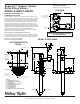
Endura II™ Outdoor Tubular
Bottle Filling Station
MODEL 4420BF1UDBFRK
TOP VIEW
OPERATING PRESSURES:
Supply water 20 – 105 psi maximum
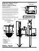
MOUNTING INSTRUCTIONS and
PLUMBING INSTRUCTIONS
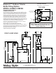
Site and drainage excavation is required for fountain installation. Refer
to owner’s manual for site preparation details. Provide solid, well-drained
surface to mount pedestal fountain (concrete pad recommended) with
adequate support (300 lb. load minimum). (8) 3/8” minimum fasteners
(not included) should be attached securely to mounting surface in order
to secure fountain, (Refer to rough-in diagram), and be sure to allow
an opening for the freeze-resistant valve in the ground as shown in the
installation instructions that accompany the fountain. (Refer to page 4 for
freeze resistant valve installation). NOTE: Pet Fountain will not be freeze
resistant. Refer to local codes for any additional requirements.
Locate and install plumbing through ground as required. Assemble
fountain to prepared site and mounting pad.
NOTE: Fountain is not furnished with service valve.
Position pedestal over plumbing and secure base to fasteners. Remove
access panels and connect supply and water lines. Turn on water supply
and check for leaks. Refer to owner’s manual for detailed instructions.
Reassemble access panels to pedestal.
Trap and service stop not included.
NOTE: PET FOUNTAIN WILL NOT BE
FREEZE RESISTANT
®
FRONT & SIDE VIEWS
*
* ADA Requirement
LEGEND
A = ACCESS PANEL (8” X 10”)
B = REMOVABLE BOTTOM COVER
C = 1” PVC DRAIN
D = PRESSURE FITTING 1-1/4” x 3/4”
E = CONNECTOR 1-1/4” to 1-1/4”
F = 1-1/4” DRAIN TUBE
G = AIR CONTROL LINE
H = 1/4” WATER LINE
J = CONNECTOR FOR AIR CONTROL LINE
4"
102m
m
FROST
LINE
5 CUBIC FEET
POROUS FILL
( LARGE BROKEN FILL )
DRAIN LINE BY INSTALLER
( AS REQUIRED BY LOCAL CODES )
WATER INLET LINE
( BY INSTALLER )
CONCRETE SLAB
BACK FILL
( DIRT )
21"
533mm
MIN.
FROST LINE DEPTH
DEPENDANT ON
GEOGRAPHIC
LOCATION AND
LOCAL
REQUIREMENTS
12"
305mm
FILL LINE
MIN.
SITE PREPARATION
DETAIL
36” Minimum
67” Maximum
26"
660mm
O
14"
356mm
(2 PL)
22"
559mm
8 - O
.500" HOLES
EQUALLY SPACED ON
TWO O12.00" B.C.