
Installation


HTHB-LR*1A, HTHB-LR*2A, HTHB-8*1A, HTHB-8*2A, HTHB-8*3A
HTHB-LR-NF*1A, HTHB-LR-NF*2A, HTHB-8-NF*1A, HTHB-8-NF*2A, HTHB-8-NF*3A
Page 4
98558C (Rev. N - 11/20)
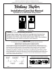
MOUNTING FRAME
CHILLER
FILTER LOCATION
(OPTIONAL)
HINGE BRACKETS
DRAIN LOCATION
UPPER PANEL
LOWER PANEL
FIG. 6
10. Lock the door in place using two set screws (provided) on the side of the panel, and a ¼ x 20 bolt through the front of the panel into the nut in the
frame.
11. (Filtered units only) Install lter cartridge, remove lter from carton, remove protective cap, attach lter to lter head by rmly inserting into head
and rotating lter clockwise.
12. Turn water supply on and inspect for leaks. Fix all leaks before continuing.
13. Once unit has been inspected for leaks, and any leaks found corrected, plug Bottle Filler into wall box recepticale (power cord not supplied on
220V models). Be sure to reinstall fuse to the circuit or switch the circuit breaker back to the “ON” position.
14a. (Filtered units) Once power is applied to Bottle Filler, the GREEN LED light should illuminate showing good lter status along with the LCD Bottle
Counter.
14b. (Non Filtered units) Once power is applied to Bottle Filler, the LCD Bottle Counter should illuminate.
15. Verify proper dispensing by placing cup, hand, or any opaque object in front of sensor area and verify water dispenses.
Note: The initial dispenses might have air in line which may cause a sputter. This will be eliminated once all air is purged from the line. A steady
stream of water assures all air is removed. The sensor has a 30 second maximum ON time. It may be necessary to step away from beam a few times
to allow chiller tank to rell. Check for leaks.
16. Mount the lower panel to the mounting frame, aligning holes in the hinge brackets with holes in the mounting frame (three places). Mount with
adequate size screws (not provided). Close the door and verify that the lock brackets on the side of the panel align with the slots on the mounting
frame. If adjustments need to be made, open the door and loosen the three screws on the hinge and adjust accordingly and then retighten the
screws.
17. Lock the lower door in place using two set screws (provided) on the side of the panel.
WALL BOX RECEPTACLE
JUNCTION BOX
LOCATION