
Installation Sheet


98765C (Rev. C - 9/11)
HTHBSM-1A, HTHBSMWF-1A,
Page 4
Plumbing Connections
• Ensure lines and ports remain clean and free of contaminants during assembly.
• Purge each component if necessary.
• To ensure quick-connect connections seal properly, follow instructions per Figure 2.
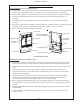
Connect Electrical Power:
1. Plug Power Cord into wall outlet.
2. Confirm unit is on:
2.1.
Filtered Units: Both the Filter Status Green LED and the Bottle Counter LCD on the Nameplate are
illuminated.
2.2. Non-Filtered Units: The Bottle Counter LCD on the Nameplate is illuminated.
3. Ensure water dispenses: Activate unit by placing cup, hand or an opaque object in front of Sensor Lens and
water should flow. It is normal for the water stream to sputter with air when the unit is new or a new filter
cartridge is installed.
4. Ensure a steady water flow is obtained: Activate unit per above and hold until all air entrapped in lines and filter
is purged. Since unit only dispenses water for 20 seconds per activation, multiple activations may be
required.
5. Inspect for leaks and if any found, unplug unit and correct before continuing.
6. If setting up the Control Board for the first time, go to Setting the Control Board (below) before continuing.
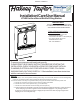
7. Place Bottom Cover in position on underside of unit with long tab against wall and slide up into Back Panel
opening. Secure with two supplied Allen head screws using a 5/32" hex-wrench (not supplied).
8. For a clean appearance, gather and loop any extra Power Cord and secure to the underside of Bottom Cover
with supplied adhesive backed clip.
Instruction for Use
1. To activate water flow, position mouth of water bottle or container under Dispensing Nozzle and in a continuous
motion, swing and hold container in front of Sensor Lens. Hold until container is filled to level desired.
2. To stop water flow, pull container away from Sensor Lens.
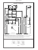
1. Connect water supply line to unit:
1.1.
Filtered Units: Connect the 3/8" O.D. Polytube (supplied factory attached on the Filter Head inlet
port) to the 3/8" Compression end of Service Stop Valve.
1.2.
Non-filtered Units: Connect the 3/8"O.D. Polytube with Insulation to the 3/8" Compression end of
Service Stop Valve.
2. Connect water supply line from Filter:
2.1.
Filtered Units: Connect the quick-connect Reducing Union Adapter Fitting, located at end of 3/8"O.D.
Polytube with Insulation, to the ¼” O.D. polytube (supplied factory attached on the Filter Head outlet
port).
2.2.
Non-filtered Units: No connections necessary.
3. Connect the 1-1/4"O.D. Drain Tray Outlet to the in-wall Drain Line using a Slip Joint Drain Union or
compression clamp (not supplied). Tighten all connections water tight.
4. Install new Filter Cartridge by removing its protective cap, inserting into Filter Head and rotating Filter
Cartridge clockwise until it bottoms-out into Filter Head.
5. Turn water supply on, inspect for leaks and correct any leaks before continuing.
Connect Plumbing Lines
Changing the Filter
1. Remove the Bottom Cover of the Bottle Filler by removing the two (2) screws.
2. Remove filter from head by rotating filter counterclockwise.
3. Remove new filter from carton, remove protective cap; cap may be placed on an old filter to reduce the
chance of the water spilling from filter housing.
4. Attach filter to filter head by firmly inserting into head and rotating filter clockwise.
5. Activate sensor on Bottle Filler until approximately 1 gallon of water is dispensed. This flushing procedure purges
air and fine carbon particles from the filter.