
Specification Sheet
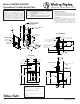

FINISHED FLOOR
1"
25mm
11"
279mm
4 1/2"
114mm
31 1/4"
794mm
HRF-ER
37 1/4"
946mm
HRF-SR
33 1/2"
851mm
HRF-ER
39 1/2"
1004mm
HRF-SR
12 1/4"
311mm
HRF-SR
18"
457mm
HRF-ER
5/8"
16mm
12"
305mm
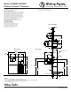
MINIMUM DEPTH
BACK WALL LINE
WALL LINE
9 3/8"
238mm
5 5/8"
143mm
18 3/4"
476mm
1 1/8"
29mm
3 1/8"
79mm
A
B
D
C
38 1/2"
978mm
20 3/8"
518mm
20 7/16"
519mm
12 1/8"
308mm
12 1/8"
308mm
3 13/16"
97mm
6 5/8"
168mm
8"
203mm
Model HTHBWF-HRFSER
Filtered Contour™ Fountain
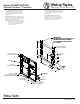
WALL OPENING
IMPORTANT: It is necessary to create a wall opening 37 1/2” W
x 37 3/4” H and 4 1/2” above the oor line.
MOUNTING INSTRUCTIONS
Refer to rough-in for location of plumbing and electrical sources.
The support frame is to be installed rst. The shelf for the water
chiller should be assembled to the wall frame, and then place
chiller into position. Hang upper fountain panel to hanger on
frame. Fountains are to be attached to panel and wall frame.
Water service lines, waste lines and electrical are assembled as
required. The bottom panel is attached last, after a nal check
for leaks and correct functions of fountains and chiller.
(For details see the installation instructions.)
Installation required trap to be install in wall. Trap and
service stop not included.
OPERATING PRESSURES:
Supply water - 105 psi maximum
Rated for Indoor Use Only
Satisfying Thirsts Since 1912
FRONT VIEW
TOP & SIDE VIEWS
ELECTRICAL DATA
Junction box for a (3) wire 10 AMP branch
circuit. Standard 120 volt, 60 Hz, single phase.
Printed in the U.S.A.
LEGEND:
A = 1/4” O.D. TUBE CONNECT (CHILLER WATER OUTLET)
B = 3/8” O.D. TUBE CONNECT (CHILLER WATER INLET) SHUT OFF VALVE BY OTHERS
C = 1-1/2” WASTE TUBE (ELBOW & TRAP NOT PROVIDED)
D = ELECTRICAL INLET
Page 3
WALL LAYOUT
Minimum 40 psi supply line pressure required
in special circumstances where both sides of
bi-level are in use simultaneously to ensure
adequate stream height. Use of water lter in
sthis situation is not recommended.
C