
Specification Sheet

Model HTHBWF-HRFSER
Filtered Contour™ Fountain
Satisfying Thirsts Since 1912
Printed in the U.S.A.
Page 4
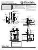
1. Cut a rectangular wall opening 37-1/2” (953mm) W x
37-3/4” (959mm) H and 4-1/2” (114mm) above the
oor line. The dimensions are required to obtain
proper rim and bubbler heights for compliance with
ANSI standard A117.1.
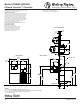
2. Reinforce the wall opening on all sides to adequately
support the water fountain. This reinforcement must
support up to 150 lbs. static load and provide a means
for securing the frame assembly in place.
NOTE: Building construction must allow for adequate
air ow on both sides, top and back of chiller.
A minimum of 4” (102mm) on both sides and
top is required. See Chiller installation for
additional instructions.
3. Install plumbing and electrical rough-ins. A junction
box for a (3) wire, 10 amp branch circuit is provided on
the inside of the chiller. (Standard 120 Volts, 60 Hz,
and single phase.)
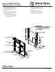
4. Remove frames and related hardware from
packaging. Release the two shelf rods by cutting
cable ties. Attach the two frames together through the
upright supports with (4) 5/16” x 3/4” (19mm) long
bolts and nuts (provided). Tighten securely.
5/16" SCREWS OR BOLTS
(12 REQ'D-NOT PROVIDED)
FRAME
P/N 27049C &
P/N 27050C
5/16" HEX NUT
(4 REQ'D - NOT PROVIDED)
SCREWS OR BOLTS
(NOT PROVIDED)
BOLT FRAMES TOGETHER
WITH 5/16" X 3/4" (19mm) BOLTS
(4 REQ'D- NOT PROVIDED)
37 3/4"
959mm
4 1/2"
14mm
37 1/2"
953mm
5 1/8"
130mm
8"
203mm
1 1/8"
29mm
TO FLOOR LINE
BACK OF WALL
TO BE 12"
(305mm) MIN
DEPTH
FLOOR LINE
WOOD OR STEEL FRAME
SHOWN (NOT PROVIDED)
ELECTRICAL INLET
LOCATION ON
CHILLER
INSTALL (3) SCREWS
(P/N 111008343890) IN FRAME
BEFORE INSTALLING IN OPENING
HOOK RODS (2)
P/N 101567443730
IMPORTANT:
DOUBLE STUD OR 3 IN CHES (7 6mm)
BETWEEN MOUNTI NG FRAMES
IF PLACED NEXT TO A BOTTLE
FI LLER UNI T
CHILLER SHELF
P/N 27638C
FRAME