E6X Manual Warnings 1. This system is capable of controlling either “intelligent” igniters which have in-built dwell control or “dumb” igniters which rely on the ECU to control dwell. This allows standard igniters to be used in many cases. Most standard igniters are dumb igniters. However, it is very important to set the system up to match the type of igniter used.
E6X Manual Contents INTRODUCTION .................................................................................................................... 7 SECTION 1 GETTING STARTED ............................................................................... 11 CHAPTER 1 Haltech ECU Installation ............................................................................... 11 1.1 The ECU and associated hardware............................................................................. 11 1.
E6X Manual 3.1.2.4 Ignition Correction Maps ............................................................................. 37 3.1.3 The Set-up Menu................................................................................................. 38 3.1.4 The Options Menu............................................................................................... 38 3.2 Online and Offline Operation..................................................................................... 38 3.2.1 Going Online ....
E6X Manual CHAPTER 6 Starting the Engine......................................................................................... 65 6.1 Calibrating the Throttle Position Sensor .................................................................... 65 6.2 Checking the Trigger.................................................................................................. 65 6.3 Checking the Base Timing ......................................................................................... 65 6.
E6X Manual 12.2 The PWM Options Page........................................................................................... 87 CHAPTER 13 Digital Outputs & PWM Outputs................................................................. 88 13.1 Turbo Waste Gate Control (TWG)........................................................................... 88 13.2 Bypass Air Control (BAC) Valve ............................................................................ 89 13.3 Dual Intake Valve Control (DIV)......
E6X Manual Under copyright law, neither accompanying software may be reduced to electronic form, herein, without prior written Ltd trading as Haltech. Copyright 2004 this manual nor its copied, translated or except as specified consent of Lockin Pty Lockin Pty Ltd A.B.N. 68 061 744 303 Also trading as HALTECH 10 Bay Road Taren Point, NSW 2229 Australia Ph: (+61) (02) 9525 2400 Fax: (+61) (02) 9525 2991 Sales@haltech.com www.haltech.com MS_DOS is a registered trademark of Microsoft Corporation.
E6X Manual Introduction Congratulations on your decision to choose a Haltech Engine Management System. Haltech EFI systems have been successfully installed on thousands of vehicles, from power offshore boats to twin-turbo Ferraris, from pylon racing aircraft to jet skis and snowmobiles. Over the past decade, many motor-sport enthusiasts have discovered that the Haltech computer is easy to use and performs well by enabling users to precisely control ignition timing and fuel delivery.
E6X Manual DO NOT CHARGE THE BATTERY WITH A 24VOLT TRUCK CHARGER OR REVERSE THE POLARITY OF THE BATTERY OR ANY CHARGING UNIT DO NOT CHANGE THE BATTERY WITH THE ENGINE RUNNING AS THIS COULD EXPOSE THE ECU TO AN UNREGULATED POWER SUPPLY THAT COULD DESTROY THE ECU AND OTHER ELECTRICAL EQUIPMENT. ALL FUEL SYSTEM COMPONENTS AND WIRING SHOULD BE MOUNTED AWAY FROM HEAT SOURCES, SHIELDED IF NECESSARY, AND WELL VENTED. MAKE SURE THERE ARE NO LEAKS IN THE FUEL SYSTEM AND THAT ALL CONNECTIONS ARE SECURE.
E6X Manual Wire Cutters and Pliers Crimping Tool and assorted terminals Drill with assorted drill bits 3/8" NPT Tap 14mm x 1.5 Tap Electrical Tape or Heat Shrink tubing Teflon pipe sealing tape Nylon cable ties Jeweller’s file (may be needed for mounting Throttle Position Sensor) Mounting hardware for ECU and relays (mounts/bolts/screws) IBM-PC compatible computer (preferably laptop) with at least 640kb, one disk drive and an RS232 serial port.
E6X Manual Injection pulses usually occur one or more times per engine cycle. The ECU uses a trigger signal locked to engine speed in order to determine when to inject. When it receives an appropriate trigger, the ECU applies a magnetising current to the injector coils for precisely as long as the final computed injection time, providing an extremely accurate delivery of fuel that will exactly suit the engine's needs. The ignition timing is determined in a similar way to the fuel needs.
E6X Manual SECTION 1 CHAPTER 1 Getting Started HALTECH ECU INSTALLATION 1.
E6X Manual 1.3 Expanded Installation Guide 1.3.1 Manifold Absolute Pressure (MAP) Sensor The MAP sensor is used to convert the manifold pressure into an electrical signal for the ECU to use. The MAP sensor is used to measure engine load or barometric pressure depending on the application. The sensor works in absolute pressure that means when the sensor is used to measure manifold pressure, the pressure reading in the manifold does not need compensation due to changes in barometric pressure.
E6X Manual The MAP sensor is usually mounted high on the engine bay firewall or inner guard using two screws and with the hose nipple facing outwards. Connect the sensor to the inlet manifold via a short length of vacuum hose and fasten with either hose clamps or nylon cable ties. Connect the sensor to the main wiring harness using the appropriate plug. (For 1 Bar sensors the plug is green, for 2 and 3 Bar sensors the plug is orange).
E6X Manual adapter is sometimes necessary. In some engines only one temperature sensor hole exists and is used for the dashboard gauge sender. It is usually possible to install a tee-piece to allow both the dashboard sender and the Haltech sender to share access to the same threaded hole.
E6X Manual Once a suitable position has been located for the air temperature sensor a hole should be drilled and tapped to accept the sensor. Remove the manifold or inlet tract from the engine before machining the sensor mount. Do not allow any metal particles to enter the inlet manifold of the engine as these will be drawn into the engine and damage it. Wash all components before reassembly. 1.3.
E6X Manual 1.3.5 Mount Ignition Module. The ignition module is used to drive the high currents required to energize the ignition coils. All vehicles that have electronic ignition control will have an ignition module or ignitor that may be compatible with the ECU’s ignition outputs, if the existing ignition module is not compatible (if you are not sure please contact your haltech dealer) installation of a new ignition module will be required.
E6X Manual or cut a new hole to suit. Use a rubber grommet or similar device to protect the harness from being damaged by rubbing on the sharp edge of the hole. WARNING: DO NOT ALLOW THE HARNESS TO TOUCH HOT EXHAUST PARTS INCLUDING MANIFOLDS OR TURBOCHARGERS. TRY TO ROUTE THE MAIN HARNESS AWAY FROM HIGH VOLTAGE IGNITION LEADS. UNDER NO CIRCUMSTANCES RUN ANY WIRING PARALLEL TO, OR IN CONTACT WITH THE IGNITION LEADS. Note: Be neat. Run the harness in a tidy fashion.
E6X Manual 1.3.9 Fuse Block Assembly The fuse block assembly holds the fuses that protect the various components of the Haltech system. The fuse block is supplied from the factory with fuses installed. The fuse ratings are shown in the diagram and should not be changed except in special circumstances, as these have been selected for best protection. In some applications where multiple low impedance injectors are being used, the main 3A ECU fuse may blow.
E6X Manual Red (Battery Supply +12V) Locate a source of continuous +12 volts and connect the red wire. Connecting direct to the positive battery terminal is suggested. Grey (Ignition Switched +12V) The grey wire is used to control the operation of the ECU power relay. It needs to be connected so that it sees 12V only when the ignition switch is on and during cranking. This wire does not draw a large amount of current (< 0.5A).
E6X Manual It does not matter which example is used, both will operate correctly. Note that the orange wires are connected internally within the loom when the relay is closed. As a result it does not matter which orange wire is used to connect to the fuel pump. 1.3.12 Install and connect Optional Idle Speed Motor If you are not using the Idle Speed Control, tie the loom connector back neatly in the engine bay.
E6X Manual PIN A B C D E F FUNCTION GROUND Trigger or Trigger Positive Trigger Negative Home Negative Home or Home Positive +13.8 V DC 1.3.15 Connect the ECU The ECU can now be connected, be sure to engage the clip on the main connector. The system can now be tested as described in the following chapters.
E6X Manual CHAPTER 2 INSTALLING THE SOFTWARE Now that your ECU is installed the programming software must be installed so that tuning can begin. This Chapter will explain how to install and run the Haltech Programming Software. 2.1 Computer Requirements The computer required to program the Haltech E6X can be any IBM-PC compatible personal computer from the XT onwards (i.e. the AT, 386, 486 or Pentium computers). The requirements are fairly modest.
E6X Manual To run the Install program type:! INSTALL and then press the Enter Key. The Install program will now run. Follow the instructions given. When it is finished, the installation program will tell you if the installation is successful. If it was not, consult the trouble shooting section of this manual in the Appendix. The Programming software is now ready to run. 2.2.
E6X Manual E6X and then press the Enter Key. You must now type: E6X/A and then press the Enter Key. The “/A” tells the program you have an Azerty keyboard. The program will adjust accordingly. 2.3 Using the Software in Windows The following explains how to use the programming software in a windows 95 or later operating system, if you are running the software in MS-DOS, windows 3.x or if you have any problems running the software in the windows environment, follow the instructions in 2.
E6X Manual A window will appear (as shown below). Double click the icon labeled “3½ Floppy (A:)”. A window will appear (as shown below). Double click the file icon labeled “install”.
E6X Manual A window will appear (as shown below). This is a MS-DOS window. When the window shows finished in the window title bar (as shown below), dismiss all the windows by clicking the “X” button at the top right hand corner of each window. Now that the Software has been installed a shortcut can be created and placed on the desktop that will launch the installed software. Right click in the empty desktop and a small menu will appear (like that shown below on the left).
E6X Manual Single click the “Browse” button to navigate to the location of the programming software. Use the “Parent Folder Button” (shown below on the right) and the folders that appear in the window to navigate to the “Haltech” folder and then the “E6X” folder created by the “install” program. Select the “E6X” icon (shown below left) and click the “Open” button at the bottom right of the window.
E6X Manual The two remaining windows that appear can be dismissed using the “Next” or “Finish” buttons found at the bottom of the windows. Now the Desktop should have an icon similar to that shown below in addition to all the previously existing icons. Now that the software is installed and a shortcut has been placed on the desktop the software can be launched by double left clicking the shortcut icon.
E6X Manual 2.3.2 Azerty Keyboards in Windows Most countries use a keyboard where the first six letter keys across the top row are: “QWERTY” This is called a “Qwerty” keyboard. Some countries use an alternative, which is called an “Azerty” keyboard, where the Q and W keys are swapped with the A and Z keys respectively. If you have an Azerty keyboard, you need to make a change to the settings of the Shortcut file created previously.
E6X Manual Now when the shortcut is used to launch the programming software the software will recognise the “Azerty” Keyboard.
E6X Manual 2.4 The Program Set-up Page To complete the installation of the programming software the Program Set-up page must be configured to suit the computer you are using. Start the Software as described above. When the Title page appears: Press N This will start the Software in the “Offline” mode. The Set-up Window is accessed from the Set-up menu: Press ALT-S There are two setting in the programming set-up page: The display options and the communications port configuration. 2.4.
E6X Manual CHAPTER 3 OPERATING THE SOFTWARE Once the ECU is installed, the programming software allows the user to change the settings currently stored in the ECU.
E6X Manual 3.1.1.1 Load Map Load Map allows the user to load a file that contains all the “set-up” and “map” data the ECU requires to run a particular engine. This file has been saved during a previous tuning session when the programming PC was connected to the ECU. When the ECU is “Offline”, the Load Map function can be used to load the information from an E6X map file (denoted by the .6XM file extension) into the front-end software to view its contents.
E6X Manual When the ECU is “Online” the horizontal black bar will gradually change colour from left to right indicating the progress of the load process. When the load process is complete a window will appear with the map details: Press Enter The screen will flash and then return to the title page. 3.1.1.2 Save Map The ECU programming software allows the user to save all the information in the ECU to a file on the programming PC.
E6X Manual 3.1.1.3 Import Map Import Map allows the user to import “map” data from other Haltech ECU maps such as E6K, F9, IG5, E6S, E6A and E6 map files. When the Import Map item is selected a sub-menu will appear to the right of the current menu. This menu has the following items: - Import Dual Map - Import Fuel and Ignition - Import Fuel Map - Import Ignition Map When any of these sub-menu items is selected a window will appear with a series of numbered options (as shown below).
E6X Manual 3.1.1.5 Quit Quit allows the user to leave the programming software and return to the operating system. The user can also quit the software using the quit “Hot-Key”: Press CRTL-Q 3.1.2 The Map Menu The map menu allows access to the maps contained in the ECU. The following is a description of the map menu and is not a complete description of the maps, for more information on all the maps available and their function refer to To open the map menu Press ALT-M.
E6X Manual The individual ranges represent different engine speeds, in the example below the map shown is from the 2000rpm range. The Fuel map menu item will open a sub-menu which allows access to all the fuel map ranges from 0 –8500rpm. The keys: N for Next and P for previous Allow the user to cycle through all the available rpm ranges and allows access to the rpm ranges not accessible via the sub-menu. 3.1.2.
E6X Manual 3.1.3 The Set-up Menu The set-up menu allows access to the ECU set-up pages (which contain most of the information about the engine that the ECU is to control) and the program set-up page.
E6X Manual It is advised that first time users familiarise themselves with the software in the “Offline” mode before “Online” operation is attempted. Most features of the software are available in the “Offline” mode so that the user can learn the controls for navigating the software. The only features not available “Offline” are: The Engine Data Page and the Calibrate Throttle function, these features require communications with the ECU.
E6X Manual The programming software requests the ECU to send the current firmware series and version numbers and then the maps currently stored in the ECU. The maps will take a short time to upload to the programming PC (as shown): When the progress bar reaches 100% the programming software has finished uploading the data from the ECU and the user can start to use the programming software to set-up and tune the engine.
E6X Manual If a sensor reading displays a fault condition like that of the coolant temperature in the above picture it means that the ECU has detected that there is a problem with the sensor or the wiring and that that part of the installation should be checked. In the case above the coolant sensor has been disconnected and the circuit is open. Check all the sensors for operation as far as is possible. 3.
E6X Manual CHAPTER 4 CONFIGURING THE ECU 4.1 Using the ECU Set-up pages The Set-up pages of the programming software tell the ECU essential information about the engine which it is to control. NOTE: The set-up pages are where tuning should begin, it is important to configure the ECU before any attempt is made to start and operate the engine. The set-up page is made up of “fields”. Each field can have a number of settings.
E6X Manual 4.2.1 Main set-up Page The main set-up page contains basic engine information. The Main Set-up Page is accessed via the set-up menu or using: CTRL-M from anywhere in the programming software. The fields in the main set-up page are as follows: Cylinders The number of cylinders needs to be entered here. This parameter is used to determine the engine speed and other fuel and ignition requirements.
E6X Manual Road Speed Value This value calibrates the Road Speed reading. The value represents the number of pulses received from the road-speed sensor over a distance of 1 km. 4.2.2 Fuel Set-up Page The fuel set-up page contains information about the fuel system. The Fuel Set-up Page is accessed via the set-up menu. The fields in the fuel set-up page are as follows: Ign / By Ignition Divide By is the number of ignition pulses that will be counted until the next injection pulse.
E6X Manual Post Start Temp Limit This field sets the temperature at which the post start correction map is either enabled or disabled. The following field “Above/Below” sets whether the enabled state corresponds to a temperature above or below the Post Start Temp Limit. The Post Start correction map will apply correction to the injection times from when the motor is started to when the engine temperature reaches the Post Start Temp limit.
E6X Manual Barometric Pressure Lock at xxxx (mBars) This field contains the barometric pressure value at which the ECU is to be locked if enabled by the field “Barometric Lock”. WARNING: BAROMETRIC CORRECTION IS A POWERFUL TOOL WHEN USED PROPERLY BUT CAN CAUSE SERIOUS DAMAGE TO ENGINES WHEN IT IS CONFIGURED INCORRECTLY. FOR A FULL DESCRIPTION OF THE BAROMETRIC CORRECTION AVAILABLE WITH THIS ECU REFER TO 9.
E6X Manual During cranking check that there is ignition and that the timing mark on the pulley wheel does not jump erratically, if there is no ignition or the timing mark jumps erratically increase the gain until the timing mark is steady. This should only be done when the installation is complete. Home Input This field is only applicable in some direct fire ignition, sequential or batch injection installations. This field has the same options as "Trigger Input".
E6X Manual Tooth Offset This field is only applicable if the trigger type is: Multi-tooth or Motronic. The offset is the number of teeth the synchronisation event occurs prior to the trigger Home Window Teeth This field is only applicable if the trigger type is Nissan. The “home window teeth” is the number of teeth counted during the home window. Nissan Tooth Offset This field is only applicable if the trigger type is Nissan.
E6X Manual This field defines the duty cycle high time when using the constant duty output type with a smart igniter. For the EB023 smart igniter the duty cycle high time is 70% with a corresponding 30% low time. NOTE: Now that the ignition set-up is correct the ignition system may be connected to the ECU. Be sure that the ECU is reset (by turning the key “off” then “on”) before you connect the ignition system to be sure that the ECU has enabled any changes made to the set-up. 4.2.
E6X Manual WARNING: WHEN CONFIGURING YOUR SYSTEM TAKE CARE TO SET THE SPARE INPUT FUNCTION CORRECTLY. IF THE SPARE INPUT FUNCTION FIELD IS SET TO BARO. SENSOR EXTERNAL AND THE BARO SENSOR IS DISCONNECTED THE ECU MAY PERFORM INCORRECT BAROMETRIC CORRECTION. IF YOU ARE USING AN EXTERNAL BARO. SENSOR AND REMOVE IT BE SURE TO RECONFIGURE THE SPARE INPUT FUNCTION TO GENERAL. 2nd MAP Sensor This field is only accessible when the Exhaust MAP Sensor is selected on the Spare Input Function.
E6X Manual Ignition Bypass Staging Signal Tacho Output Ignition Toggle Bypass signal compatible with some General Motors ignition systems. This function allows the ignition system to provide the spark at 10° BTDC at cranking speeds (below 500rpm). This aids starting. Logic output that indicates Staging conditions. If Staging is selected, and the Staged injector are firing, this signal will be high (5 volts), otherwise it will be low (~ 0 volts).
E6X Manual Never Always Enable with Aux. In This causes the ECU to only use the primary base fuel and ignition maps. This causes the ECU to only use the secondary base fuel and ignition maps. This causes the ECU to use the primary base fuel and ignition maps when the Aux. In is not connected to ground. The ECU uses the secondary base fuel and ignition maps when the Aux. In is connected to ground. Note: The Aux. In field in the Input/Output Set-up page must be set to Dual Maps Input. Refer to 4.2.
E6X Manual CHAPTER 5 HALTECH MAPS 5.1 What are maps? The Fuel and Ignition requirements of an engine at a given point in time are based on the operating conditions at that time. The operating conditions the ECU uses are: manifold pressure, barometric pressure, air temperature, coolant temperature, throttle position and engine position.
E6X Manual The map above shows the fuel requirements for the engine across the load range at 3000rpm. The yellow bar shows that the engine requires 4.096ms of fuel at –50kPa and 3000rpm. The Ignition Maps work in a similar way, except that it is the ignition advance that is stored in the map instead of the injection time. The programming software presents the maps in a bar graph formation to make it easy to visualise fuelling and ignition.
E6X Manual This will leave the selected bar highlighted and will cause the next bar to the left or right to become highlighted. The up and down cursor key result in a relatively small change in height of the bar or bars selected. To facilitate quick tuning there are 4 key combinations that allow different increments in bar height. The key combinations and bar increments: Key Combination ↑ or ↓ PgUp or PgDn Shift-PgUp or Shift-PgDn Ctrl-PgUp or Ctrl-PgUp Increment 0.016ms 0.128ms 0.5120ms 1.0240ms 5.2.
E6X Manual 5.2.4 Linearise When tuning it is often useful to be able to set two load points with a given value and approximate the fuel requirements between those two points with a straight line. The linearise function allows the user set approximate fuel values based on a straight-line approximations as shown below: The above map shows the highlighted bar as much higher than the rest. In this case the estimated fuel requirements for full load operation in this range is 12.
E6X Manual The map above shows the heights of the bars after the linearise function has been applied. The linearise function calculates the height of the bars between the two extreme bars based on a line drawn between tops of the two extreme bars, the result is a linear fuel map. 5.2.5 Numeric Mode The programming software offers the ability to tune the maps using a spreadsheet style map called “Numeric Mode”.
E6X Manual 5.3 The Haltech Maps The Maps that the ECU uses to calculate fuel and ignition requirements are explained in detail here. 5.3.1 Fuel Map – 3-Dimensional The fuel map is accessed through the menu structure under the maps menu or using the hotkey CTRL-F. The Base fuel map represents the reference on which all fuel corrections are made to calculate the final fuel requirement for the given engine load and engine speed.
E6X Manual 5.3.4 Fuel Correction Maps The following is an explanation of maps that are used to correct the base fuel quantity based on the environmental conditions. 5.3.4.1 Coolant Temperature Correction The coolant temperature correction map is accessed through the menu structure and can be found under “Fuel Correction Maps” in the maps menu. The coolant temperature correction map is used to adjust the fuelling based on the coolant temperature measured by the ECU.
E6X Manual 5.3.4.6 Barometric Pressure Map The barometric pressure correction map is accessed through the menu structure and can be found under “Fuel Correction Maps” in the maps menu. The barometric pressure correction map is used to adjust the fuelling based on the barometric pressure measured by the ECU. The map has 32 bars distributed across barometric pressure in the range 523mBar to 1046mBar and each bar represents a percentage correction to the current calculated fuel. 5.3.4.
E6X Manual 5.3.5.3 Coolant Temperature cranking map The coolant temperature cranking map is accessed through the menu structure and can be found under “Ignition Correction Maps” in the maps menu. The coolant temperature cranking map is used to apply a set ignition angle based on the coolant temperature measured by the ECU at engine speeds below 380rpm, which are considered to be cranking speeds.
E6X Manual speed in the range 0rpm to 16000rpm and each bar represents a duty cycle fed to the bleed valve in the range 5% to 95%. 5.3.10 Torque Converter Control Map The torque converter control map is accessed through the menu structure under the maps menu and is used in conjunction with the torque converter control. Refer to 13.4 Torque Converter Clutch Lockup (TCC), p90.
E6X Manual This only identifies the map being edited, not the map being accessed by the ECU to run the engine. The active editing map can also be selected through the Dual Map set-up page. 5.5 Ignition Quick-Map Often when mapping ignition it is simpler to start with a basic ignition profile which takes into account the basic ignition requirements with respect to engine speed and load.
E6X Manual - alphabet after A adds 3 degrees of ignition advance to the full load advance under light load, up to the letter H. (H = 21°) If the engine is turbocharged or supercharged then the seventh and eighth characters specify the ignition retard the engine is to get under boost. This value is subtracted from the atmospheric pressure advance value. If the engine is not turbocharged or supercharged, then leave the name only six characters in length.
E6X Manual SECTION2 Tuning The Engine CHAPTER 6 STARTING THE ENGINE Once the ECU is installed and the set-up has been completed it is time to try to start the engine. Before cranking the engine there are a few things that need to be done. Make sure that the ECU is powered (ignition on) and the Haltech Software is online. Go to the Engine Data Page to check that the ECU is communicating properly, and that the sensors are reading correctly. Check again that the set-up information is correct. 6.
E6X Manual timing light connected to the correct cylinder). If the timing is wrong change the trigger angle (in the ignition set-up page) until the timing reads correctly. If you cannot see the timing mark you may need to estimate the trigger angle based on the relative positions of the engine and the crank position or cam position sensors and then try the test again. NOTE: Some triggers have a tooth offset setting that gives greater flexibility in setting the trigger angle.
E6X Manual Before starting the engine, go to the fuel map Range 1 (0 rpm), it is this map that the ECU will use to calculate fuel requirements during cranking. The behaviour of fuel calculation around cranking and idle differs depending on the type of load sensing used. 6.5.1 Starting the using Manifold Pressure Load Sensing Try to start the engine. At cranking speeds the manifold pressure will be close to atmospheric due to the low airflow around the throttle plate and through the idle passages.
E6X Manual The Home Key that automatically jumps to the current range in a 3-dimensional map. To jump to the current range press: HOME This will take you to the current range used at the time the Home Key was pressed. 6.5.4 Tuning for Idle The idle mixture is very sensitive to correct bar height. Idle injection times are usually around 1.5 to 2.5 ms, if the injection time at idle is much lower than this, it may become difficult to set accurate idle and cruise mixtures.
E6X Manual Full load tuning should be approached with caution. An engine at full load that is too lean may begin to detonate and destroy pistons and crankshafts. Before loading the engine, increase the heights of the right-most bars so that they are higher than the line projected by drawing a straight line from the idle and free-rev settings and through the part-load settings. WARNING: RUN THE MAP RICH, AND LEAN IT TO THE CORRECT MIXTURES.
E6X Manual CHAPTER 7 THROTTLE EFFECTS 7.1 Throttle Response Where the procedures described in the previous chapter tune for constant load running, the functions outlined in this section will improve the throttle response of your engine. The manifold pressure sensor used with the E6X is very fast. It can respond much faster than is required to track any sudden changes in load on your engine.
E6X Manual The final parameter on the Throttle Pump page is the Coolant Factor. Generally, when the engine is cold, accelerator pump values need to be increased slightly. The E6X therefore applies a coolant correction to the throttle pump in the same way as it does to the base map. The Coolant Factor may be set with values from 0 to 4. Setting it to 0 will negate all coolant correction to the throttle pump. The default setting for this parameter is 0.5. 7.
E6X Manual CHAPTER 8 COLD STARTING AND RUNNING The ECU has four features to correct fuel delivery and ignition timing to aid in starting and running a cold engine. The cold start prime map gives a cold engine an initial burst of fuel just as the engine begins cranking, the coolant correction map modifies the normal fuel injection until the engine reaches normal operating temperatures.
E6X Manual CHAPTER 9 CORRECTION FACTORS Note: The following correction factors should not be altered unless you have a detailed knowledge of your engine and the environment in which it operates. Severe damage can be done to your engine if the correction factors are not set properly. The ECU has further correction maps: inlet air temperature and battery voltage fuel correction and coolant temperature and inlet air temperature ignition correction. WARNING: MOST USERS SHOULD NEVER ADJUST THESE MAPS.
E6X Manual 9.4 The Ignition Inlet Air Temperature Map This Map allows up to 10° advance or retard of the spark timing based on the inlet air temperature. Normally this Map would not need to be used, but in some cases such as high inlet air temperatures on turbo/supercharged engine, retarding the spark may help preserve the engine. 9.5 Barometric Correction NOTE: The description that follows is targeted at advanced applications. Only limited installations use barometric compensation.
E6X Manual The ECU begins with the basic idea that there are three ways to measure barometric pressure variations. 1. The ECU uses a user programmable value for barometric pressure, regardless of the current environmental conditions. 2. The ECU uses a pressure sensor to take a barometric pressure sample from the environment when the car is first turned on and uses this value for the remainder of the time the car is operated.
E6X Manual In this case, the ECU will use the last measured pressure, which is stored in memory with the maps. To complete Method 2 follow these steps: 1. Set the Barometric Lock in the Fuel Set-up page to “disabled”. 2. Make sure the throttle position sensor is properly calibrated. It must exceed 96% throttle for this to work. Also make sure that the MAP Sensor is set correctly in the Identification. 3. Switch the ignition off. 4. Apply full throttle. 5.
E6X Manual When the ECU is configured to measure load by MAP sensor the external MAP sensor is connected to the Spare A/D input. 9.6 Post Start Enrichment On some motors, in particular rotaries there is a problem with vapour-lock (fuel which due to heating of the fuel rail has vaporised). The additional fuel at start up allows the vapour in the fuel rail to be purged through the injectors and also allow enough fuel to be injected into the motor to allow stable operation.
E6X Manual SECTION 3 Software Features CHAPTER 10 PRINTING MAPS You can print the maps and identification information to printers that accept IBM emulation mode, such as IBM compatible dot matrix printers (consult your printer manual). The Print function should work with other IBM compatible printers, but some special characters such as °, ±, etc. may not print correctly. The print function is accessed through the menu structure under the options menu.
E6X Manual CHAPTER 11 DATA LOGGING 11.1 The Data log Option Data logging is simply recording the engine data as it is received by the programming PC so that operation of the vehicle can be assessed. Data logging is particularly useful for diagnosing problems. The data log records at a nominal rate of ten times per second while the ECU is online with the programming PC. The data-logging submenu is accessed through the menu structure under the options menu. 11.1.
E6X Manual 11.1.3 Data log File Management Data log files may be saved to disk, loaded and erased in exactly the same manner as maps. From the Data log sub-menu, you can do the following: S L E - save data log to disk. This function is only relevant if you have previously performed a data log to memory. - load a data log from disk. - erase a data log from disk. When saving a Data log to disk, you should also save the Maps being used at the time of the Data log.
E6X Manual 11.1.5 Setting Up the Data log Page A data-log the data page can only display eight parameters simultaneously. To access the configuration menu press C and follow the instructions that are presented with the selection menu.
E6X Manual SECTION4 Inputs & Outputs The ECU has a number of optional inputs and outputs other than the available injection and ignition channels. These are: OUTPUTS: - Idle Speed Control - Auxiliary Out (Aux Out) - Digital Output (Digital Out 1-2) - Pulse Width Modulated Output (PWM 1-4) INPUTS: - O2 Closed Loop Control - Auxiliary In (Aux In) All the inputs and outputs have different functions: - The Idle Speed control outputs can only be used to drive a stepper motor idle control valve.
E6X Manual CHAPTER 12 OUTPUT OPTIONS SET-UP The output options and PWM set-up pages are used to program settings for the output functions of the ECU in a similar way as the set-up pages are programmed. Refer to 4.1 Using the ECU Set-up pages, p42. 12.1 The Output Options Page The output options page contains the set-up information for idle control, O2 closed loop fuel control and the digital 1 and digital 2 outputs.
E6X Manual RPM Target Idle RPM + Cold Idle-Up RPM + Start RPM Target Idle RPM + Cold Idle-Up RPM Target Idle RPM Engine Cold Engine Warm 0 5-10 mins 20sec Time Number of Steps This field controls the number of steps that the idle control will operate over.
E6X Manual Hot Min Position Exactly the same as for when the engine is cold, except the value is used for when the engine is hot, that is the temperature is above the Cold Temperature Limit. Cold Opening position (%) This is the opening position as a percentage of where the stepper motor will return to when it is about to attempt to gain control of the engine.
E6X Manual sensor. If the closed loop function is responding erratically, constantly overdriving to the adjustment limits, or if there is insufficient oscillation in the air-fuel ratio for the catalytic converter to operate, increasing this parameter may help. If it is set too high, the feedback loop will be noticeably slow to respond to change.
E6X Manual To change the digital output function change the title field at the top of the digital output window. When the title is changed the remaining fields in the window will also change to reflect the parameters of the new selected option. 12.2 The PWM Options Page The PWM options page contains the set-up information for the four PWM (pulse width modulation) outputs. The PWM options page is accessed via the options menu or using: CTRL-W from anywhere in the programming software.
E6X Manual CHAPTER 13 DIGITAL OUTPUTS & PWM OUTPUTS The digital outputs and PWM outputs can be programmed to operate a wide variety of functions. Some of the functions have restrictions to their operation.
E6X Manual Boost Limit Update Eng. Data of map one and map two. The conditions for waste-gate map usage when “Advanced” is selected are: If the ECU is using the primary fuel and ignition maps then the ECU will use waste-gate map one to control boost. If the ECU is using the secondary fuel and ignition maps then the ECU will use waste-gate map two to control boost. Refer to 4.2.5 Dual Map Set-Up, p51.
E6X Manual Off RPM should be set to at least 200 RPM below On RPM, forcing hysteresis in the switching to prevent the solenoid from oscillating when the engine speed is at the switch point. The second configuration is to enable the solenoid for a range of engine speed and to disable the solenoid when the engine speed falls outside this range.
E6X Manual 13.7 Shift Light Illumination (SL) This function can be used to drive a light or buzzer to indicate the engine speed exceeds a programmed level. Light On RPM 0 – 16000 RPM This parameter sets the engine speed at which the output will be enabled. 13.8 Auxiliary Fuel Pump (AP) This function causes the output to turn on when the measured engine load or engine speed exceed the programmed values.
E6X Manual 13.10 Staging Signal Function (SS) This function causes the output to turn on when the engine load exceeds the “Staging Bar” value. The staging bar is set in the fuel set-up page refer to 4.2.2 Fuel Set-up Page, p44. There are no programmable parameters associated with this function. 13.11 Turbo Timer (TT) The turbo timer function allows the ECU to continue running the engine after the ignition has been switched off.
E6X Manual Min. Rpm Minimum Throttle Minimum Temp Ignition Retard Start-up Delay If the RPM exceeds this value the NOS system will be switched off. 100 – 16000 RPM If the RPM is below this value the NOS system will not be activated. 0 – 100 % The NOS system will be turned on above this value. 0 – 127 °C / 32 - 261 °F The NOS system will not be activated unless the engine coolant temperature is above this value. 0 – 20 °BTDC The ECU will provide an ignition retard whenever the NOS system is engaged.
E6X Manual On Coolant Temp 0 – 127 °C / 32 - 261 °F This field defines the coolant temperature above which AntiLag is operational The anti-lag system is can be enabled by a switch connected to Aux. In or by meeting all three operating conditions stated above (the last 3 fields). Once the switch is enabled, if the Throttle condition is met, the anti-lag system will be activated.
E6X Manual 13.16 VTECH This function controls the solenoid used to control the variable valve timing with which some engines are equipped. This feature acts purely to control a switching solenoid and is not capable of controlling continuously variable valve timing. On RPM Off RPM On Load Bar Off Load Bar 0 – 16000 RPM This field defines the engine speed above which the VTECH is enabled. This field must be greater than Off RPM or it will be ignored.
E6X Manual Cold Idle Temp. Cold Duty: Hot Duty: A/C Load Duty: Start-Up Duty: Active (Aux In): 0 – 127 °C / 32 - 261 °F This value is the coolant temperature above which the “hot” base duty cycle value is used and below which the “cold” base duty cycle will be used. 0 – 100 % This is the base duty cycle used when the coolant temperature is below the Cold Idle Temp value. 0 – 100 % This is the base duty cycle used when the coolant temp is above the Cold Idle Temp value.
E6X Manual Active Sw. Posn. HIGH or LOW This defines the active level or polarity of the signal. When this field is set to HIGH the active output is 12V, when the field is set to LOW the active output is 0V. There are two possible configurations for this feature: The first configuration is to have two throttle position ranges; one high and one low. In the lower range the output is inactive and in the upper range the solenoid is active.
E6X Manual SECTION 5 Appendices APPENDIX A TROUBLESHOOTING This Appendix is devoted to trouble shooting problems that may occur during installation and configuration of the ECU. To use this Appendix, identify the symptom or symptoms that best describe the problem from the list below, then follow the checklist for possible solutions. Control Program Problems • The Haltech Programming Software will not start • The Haltech Programming Software will not operate in ONLINE mode.
E6X Manual A.1 Control Program Problems Haltech Programming Software will not start The Haltech programming software should run on any computer that meets the requirements outlined in 2.1 Computer Requirements, p22. If after following the instructions outlined the program will not run, the most likely cause will be insufficient memory. If this is the case, you must make more free memory available before running the software. Run the Haltech software from the DOS prompt.
E6X Manual If the Manifold Absolute Pressure Sensor does not read near atmospheric pressure with the engine off, or if it shows a fault condition, then check that the sensor is connected correctly. Check that you have the correct model sensor and that the Identification page information has been set correctly.
E6X Manual necessary. If not using the idle air control motor then adjust the idle using the idle adjust screw on the throttle body. Check for any air leaks in the manifold. Check the ignition timing at idle and adjust if necessary. If the engine surges or hunts at idle then the mixtures and timing are wrong. Readjust the fuel maps near idle conditions. In some circumstances it may be necessary to use the Zero Throttle Map. Consult Chapter 6 [6.2] for information on using the Zero Throttle Map. A.
E6X Manual difficult to drive when cold, particularly with gear changes, try increasing the coolant correction factor for the throttle pump. An engine that will idle when warm, but fails to idle cold unless a tiny amount of throttle is applied may require idle speed control, with a fast-idle function for when the engine is cold. The E6X can control an Idle Air Control motor that will perform this function. A.9 Fuel Consumption Poor fuel consumption is a result of a too rich mixture.
E6X Manual APPENDIX B IGNITION AND INJECTION OUTPUTS B.1 Distribution of Outputs The ECU has five injection/ignition outputs, or channels. These five channels are distributed to the ignition and injection drivers that in turn are connected to IGN1-IGN4 and INJ1-INJ4 respectively. IGN DRIVER 1 IGN DRIVER 2 IGN DRIVER 3 ECU PLD IGN DRIVER 4 INJ DRIVER 1 INJ DRIVER 2 INJ DRIVER 3 INJ DRIVER 4 This configuration gives the user 4 injection drivers and 4 ignition drivers. B.
E6X Manual Note: Engines with an odd number of cylinders cannot use waste spark ignition since these engines cannot pair cylinders. If a 6 or 8 cylinder engine is equipped with a single coil per cylinder these coils can be paired and driven as a waste spark configuration. Each coil requires an ignitor but the ignitor inputs can be paired as cylinders are paired in the above description. B.2.
E6X Manual B.3 Sequential Injection Sequential injection allows fuel to be delivered to the engine at a time that produces best combustion. Since this time is different for each cylinder, sequential systems inject fuel at different engine angles for each cylinder. The ECU will control up to four separate fuel channels. This provides full sequential injection for engines up to 4 cylinders, and semisequential for 6 and 8 cylinders engines. B.3.
E6X Manual cylinders opposite in the firing order. A 6-cylinder engine with firing order 1-5-3-6-2-4 would have the following injector pairs: INJ1 INJ2 INJ3 cyl 1 and cyl 6 cyl 5 and cyl 2 cyl 3 and cyl 4 This fuel scheme requires a home signal that is driven by the crank or cam since the ECU needs to know what the engine position is in its 360° cycle. Note: Sequential injection on 5 and 10 cylinder motors is not possible with the E6X.
E6X Manual B.5 Summary Table The list that follows shows the different types of output configurations that may be employed. Note that in some cases, an Extra Driver Box is needed to provide sufficient driver power. “Standard” fuel injection is multipoint, staged or batch fire. DF is for Direct Fire. # Cyl.
E6X Manual Each coil igniter will have its own trigger. If using direct fire, a Home signal is needed for trailing ignition to be generated. Output INJ1 INJ2 IGN OUT IGN 2 IGN 3 Distributor Function Fuel (Primary) Fuel (Secondary) Leading Spark Trailing Spark Digital Output Direct Fire Function Fuel (Primary) Fuel (Secondary) Leading Spark (both) Trailing Spark front rotor Trailing Spark rear rotor B.
E6X Manual The ECU must calculate the time at which to switch the coil on to maximise energy stored in the coil just before the spark is to occur. The coil’s charge time can be determined from the coil negative signal: when the coil switches on, the coil negative voltage drops to zero, as the coil energises the voltage rises slightly until a sharp rise where the ignitor current has reached the upper limit.
E6X Manual COIL GND Negative terminal of coil Ignition system ground Output There are several versions of the Ford TFI module but these notes only refer to the type IV module. This TFI module is physically attached to the side of the distributor and connects directly to the HALL Effect pickup within the distributor. To further complicate matters there are two types of chopper wheels used inside the distributor, one that generates a normal’ PIP signal and one that generates a ‘signature’ PIP signal.
E6X Manual APPENDIX C INJECTORS C.1 Injector Impedance Injectors, when classified electrically, fall into 2 categories: Saturation Injectors this type of injector derives its name from the method used to drive it open, the coil is saturated with current to create the magnetic force used to open the injector until the injector is to be closed. This type of injector has a coil impedance > 12Ω, this means that if 12V is applied across the coil the current will not exceed 1A.
E6X Manual APPENDIX D FUEL SYSTEMS & STAGING The best ECU installation will yield poor results if the fuel system does not meet the demands of the engine. Insufficient fuel flow can lead to lean fuel mixtures and detonation that will ultimately cause serious damage to the engine. For the safety of your engine, we urge you to check your fuel system's capacity and ensure that there will be sufficient supply at all times.
E6X Manual so the absolute maximum injection time at 6000 RPM on this engine is 10 ms. If the injection time needs to be greater than this, then your fuel system cannot meet the demands of the engine. You will need to increase the fuel supply, by increasing injector size, fuel pressure, or adding extra injectors. Refer to Appendix D for details on how to increase fuel supply. As a general rule of thumb, injectors should not run beyond 85% duty cycle.
E6X Manual D.2 Fuel Requirement If you can estimate the power output of a gasoline engine, you can make a reasonable guess at the fuel flow requirement. The following is a guide to the quantity of fuel required: Every 100 hp needs around 50 lb/hr (8.0 US gal/hr) of fuel (6.6 Imp gal/hr) Every 100 kW needs around 670 cc/min (40 L/hr) of fuel This assumes a brake specific fuel consumption of 0.50. The actual fuel flow necessary by injectors and pump are likely to exceed a figure derived this way.
E6X Manual Adjust the bars around the staging point with extreme care to ensure that the engine does not lean out as the secondary injectors come in. When the Haltech ECU begins to stage it begins firing both sets of injectors at once and fires them with the same duration. This means that if both primary and secondary injectors are of the same flow rate then the first staged bar should theoretically be slightly more than half that of the last un-staged bar.
E6X Manual two regulators can be joined. Since pressure regulators work within certain flow limits, this may also save having to purchase an expensive high pressure / high flow regulator.
E6X Manual APPENDIX E TRIGGER INTERFACE The ECU is capable of accepting many different trigger patterns and trigger types. This appendix will explain the various trigger systems the ECU supports. The following fields configure the trigger input: (Refer to 4.2.3 Ignition Set-up Page, p46) Trigger Input Trigger Angle Trigger Edge Trigger Gain Trigger Type The trigger interface will be described below in terms of the above fields to simplify configuration of the ECU trigger interface. E.
E6X Manual E.1.2 Reluctor Triggers A reluctor trigger produces a signal trace that looks like an upward or positive pulse followed immediately by a downward or negative pulse and then remains flat until the next trigger tooth passes. These sensors normally only have 2 or 4 connections: trigger positive and trigger negative (home positive and home negative). A common reluctor trigger is the 24-1 trigger used on some Toyota engines.
E6X Manual effect trigger. The reluctor adaptor and its tuning is dealt with in detail in 4.2.3 Ignition Setup Page, p46. E.2 Trigger Angle The trigger angle is simply the angle before top dead centre (BTDC) at which the trigger event occurs. The trigger device used must produce at least one trigger event for each ignition event and each trigger must occur a constant angle BTDC. See Appendix E.6 Trigger Type E.
E6X Manual Some trigger devices have uneven pulse widths to indicate the position of a specific cylinder (often cylinder 1). If rising edges were used as the trigger edge then there would be a variation of 20° between the trigger for cylinder 1 and all other cylinders. This would lead to cylinder 1 being 20° more advanced than all the other cylinders. To ensure even ignition timing the trigger edge would be the falling edge and the trigger angle would be 60° BTDC.
E6X Manual E.5 Synchronisation When the ECU is configured to operate an engine that uses direct fire ignition or sequential injection, the ECU needs a reference for engine position often referred to as a “synchronising” signal or a “home” signal. When the ECU is configured to perform full sequential injection or full direct fire ignition it requires a home signal that occurs once in the full cycle (720° of crank rotation and 360° of cam rotation).
E6X Manual Grey Trigger Teeth White Home tooth After recognising the home event, the ECU will locate the first “standard” engine trigger by the tooth indicated as “Tooth Offset” which can be programmed via the Ignition Set-up page. To find the remaining “standard” trigger events, the ECU counts a number of teeth equal to the total teeth in one cam revolution, divided by the number of cylinders.
E6X Manual Note: Since the missing tooth only gives the crank position (360° crank) and not the cam position (720° crank and 360° cam) this type of trigger cannot support full sequential fuel injection or full direct fire ignition unless a cam sensor is used in conjunction with the motronic wheel. Due to the high frequency of the motronic signal and complexity of detecting the missing tooth, the maximum rpm to which the ECU will operate is 9000 rpm. Ford 36-1 motronic style wheel E.6.
E6X Manual The trigger signal consists of the same number of pulses as the engine has cylinders. The beginnings of the pulses (rising edge) are evenly spaced, but the ends of the pulses (falling edges) are not evenly spaced. The differing pulse widths enables the ECU to synchronise engine position with ignition and fuel timing, the ECU does this by counting the number of home pulses that occur during the trigger pulse.
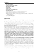
E6X Manual if Cylinder Number = 1 Number of cylinders Number of Pulses = + 1 × 4 2 if Cylinder Number is opposite of Cylinder number 1 Number of cylinders Number of Pulses = ×4 2 if (Cylinder Number = 2 and Number of Cylinders = 4) or (Cylinder Number = (2 or 3) and Number of Cylinders = 6) Number of cylinders Number of Pulses = − (Cylinder Number − 1) × 4 2 Cyl. 6 Window Cyl. 1 Window Cyl.
E6X Manual E.6.5 Subaru A Triggers (1989-2000) All factory-injected 4-cylinder Subaru engines manufactured before 2001 use a combined crank-angle/cam-angle trigger system. If a Subaru trigger is being used, select the Trigger type as “Subaru A” and connect the Cam angle sensor to the Home Input and the Crank angle sensor to the Trigger Input. Both the Trigger and Home Input should be set to Reluctor and the “Trigger angle” should be approximately 65±2° BTDC.
E6X Manual E.6.9 MGF Trigger The 4-cylinder MG-F uses a unique trigger system similar to that of the Subaru engines. This trigger system uses use a crank-angle trigger system. Select the Trigger type as “MGF” and connect the Crank angle sensor to the Trigger Input. The Trigger Input should be set to Reluctor and the “Trigger angle” should be approximately 65±2° BTDC.
E6X Manual APPENDIX F ROTOR PHASING One of the most important aspects to consider when modifying a distributor or trigger is the Rotor Phasing. Take, as an example a distributor that uses a Hall effect sensor with a chopper wheel attached to the distributor shaft, the Hall effect sensor being mounted to a plate that is rotated by a vacuum advance mechanism and by centrifugal bob weights. This is a fairly conventional set up used in many vehicles with electronic ignition.
E6X Manual APPENDIX G HALTECH E6X SPECIFICATIONS Engine Suitability • • • • Up to 16,000 rpm 1, 2, 3, 4, 5, 6, 8, 10, 12 cylinders (1-2 rotors)* 2 or 4 stroke Normally aspirated or supercharged up to 200 kPa (30psi) - Higher boost pressure MAP sensors available by special arrangement • Load sensing by throttle position or manifold pressure • Multipoint, batch-fire, staged or sequenced (up to 4 banks) injection patterns • Distributed ignition systems, or direct fire systems with 1 to 4 coils NB: Sequenti
E6X Manual • Throttle Position Sensor 10 kΩ rotary potentiometer driven from throttle shaft • Internal Barometric Pressure Sensor Barometric pressure compensation only • Engine Speed Pickup Compatible with most trigger systems: - 5 or 12 volt square wave; - Pull-to-ground (open collector) Most inductive/magnetic triggers ECU Outputs • Injector Driver 4 x Two State Programmable Peak-and-hold current limiting drivers capable of driving at: - 4Apk/1Ahold - 8Apk/2Ahold The above current specifications allow th
E6X Manual Adjustable Features • Base Fuel Map 22 Fuel ranges, every 500 RPM to 10,500, or 17 Fuel ranges, every 1000 rpm to 16,000 32 Load points per range, up to 16ms with 0.
E6X Manual • Rugged Aluminium Casing Black anodised with integral cooling fins and mounting brackets. • US or Metric Units. E6X Hardware Options • Boost Control Solenoid. • Dual Hall Effect Sensor Kit. • Extra Injector Driver Kit. • Four Wire Heated Oxygen Sensor. • Fully Terminated and Sheathed Wiring Harness In Lieu of Flying Wire Lead Harness. • Haltuner Inexpensive dash mounted Air-Fuel Ratio Meter. • Idle Air Control Motor Housing. • Idle Air Control Motor.
E6X Manual LIMITED WARRANTY Lockin Pty Ltd trading as Haltech warrants the HaltechTM Programmable Fuel Injection System to be free from defects in material or workmanship for a period of ninety days from the date of purchase. Proof of purchase, in the form of a bill of sale or receipted invoice, which indicates that the product is within the warranty period must be presented to obtain warranty service.
E6X Manual APPENDIX H WIRING DIAGRAMS 134