S3 and S4 Hall Effect Sensor Installation and Setup Procedure
E.2.3 Hall Effect Sensors The Haltech hall effect sensor is a two channel device that can be used to trigger the Haltech range of ECU’s in a wide range of applications. The most common application is in a direct fire configuration where a synchronisation event is required. As the Haltech hall effect sensor is dual channel, it can provide this synchronisation pulse as well as the trigger signal. The principle behind its operation is quite simple.
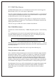
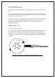
Identifying the magnets poles If you need to identify the magnet poles this can be done easily with the use of a multimeter. By powering up the sensor, using 12 volts (PIN B) and ground (PIN A) the secondary trigger channel (PIN D) can be checked to identify a south pole. Connecting the multimeter between PIN D and ground, 12 volts should be present. When a South pole is placed in front of the sensor this value will go to 0 volts.
Note: In the following examples, for ease of reference, the magnets are shown mounted on the circumference of a wheel with the Haltech Hall effect sensor oriented to one side. If so mounted the magnets need to be mounted with sufficient strength to resist centrifugal force. In practice the magnets are often mounted within the circumference of the wheel and the sensor is mounted so that its base is pointed towards the magnets in the face of the wheel.
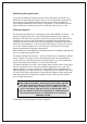
8 Cylinder For an eight cylinder 4 magnets are required in total, positioned exactly 90° apart.
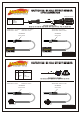
The S4 Hall Effect Sensor The S4 sensor which is identified by a way: grey cable gland operates in the following As a south pole passes the sensor face the signal in the secondary (PIN D) channel is switched to a low state. As a north pole passes the sensor a low state will only occur on the primary channel (PIN C). The set-up for this sensor is similar to the S3 except that one extra magnet is required as well as the orientation being changed.
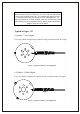
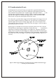
6 CYLINDER / 3 ROTOR ENGINE For a six cylinder 4 magnets are required in total. The three north poles are positioned exactly 120° apart while a south pole need to trigger the sensor before the trigger for cylinder No 1. Figure 5: Typical 6 cylinder/ 3 rotor application 8 Cylinder For an eight cylinder 5 magnets are required in total positioned exactly 90 ° apart. A south pole needs to trigger the sensor before the trigger for cylinder No 1.
E.3 Synchronisation Events Synchronisation Events (Sync Events) are required for sequential and direct fire systems. The Sync Event gives the ECU in indication of the engines position. The most common form of Sync Event is a Home Trigger. Other Sync Events a re the missing teeth on multitooth triggers. A Home Trigger is usually a separate trigger from the main trigger, but some special trigger sensors, such as the Haltech Hall Effect Sensor, can generate both signals from the one sensor.
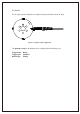
HALTECH S3 / S4 HALL EFFECT SENSOR 4 PIN CONNECTOR Looking into connector PIN CONNECT TO +13.