Haltech Wideband Controller (HWC) Manual Warning! The Oxygen Sensor used in this device gets very hot in operation. Do not touch the hot sensor. Do not let a hot sensor touch a combustible surface. Do not use the sensor with or near flammable liquids or gases. Failure to heed these warnings may result in severe burns, explosions or fires. When installed in the exhaust, the oxygen sensor MUST be connected and operating whenever the car is running.
1. Overview...................................................................................................................................... 3 2. The Haltech Wideband Controller (HWC) ................................................................................... 3 2.1. The HWC Module ................................................................................................................ 3 3. Mounting and Connecting the Wideband Controller ...................................................
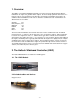
1. Overview The HWC is a stand-alone Wideband Controller used to measure the Air/Fuel Ratio (AFR) or Lambda for an engine. For gasoline-driven engines, the theoretically optimal air fuel ratio is 14.7 pounds of air for every pound of fuel. At this ratio, theoretically, all available oxygen in the air combines with all available fuel. This ratio is called the stoichiometric ratio. Stoichiometric for different fuels are as follows: Gasoline LPG (Propane) Methanol Ethanol CNG Diesel 14.7 15.5 6.4 9.0 17.2 14.
-4-
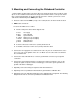
3. Mounting and Connecting the Wideband Controller 1. Find a suitable location under your vehicle where the Controller body can be mounted. Using zip ties or other suitable method, fasten the body of the Controller device securely to the framerails or other mounting points as far away from the heat of the exhaust system as the sensor cable allows. DO NOT zip-tie the HWC by the cables. 2. Route the cables from the HWC (except sensor cable) into the car interior under the dash. 3. HWC Cable connections: 3.
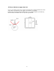
3.1 Indicator LED and Calibration button hookup: Any color LED can be used. A typical LED has 2 wires called Anode and Cathode. The Cathode side is the shorter of the 2 wires. It is connected to Ground. The Anode side will be connected to the calibration wire. Pressing the pushbutton or connecting it quickly to ground starts a free air calibration process in the HWC. MAKE SURE THE SENSOR IS IN FREE AIR FOR THAT. See chapter 6 for details. 3.2 Mounting the sensor using a Bung.
Do NOT install the Bung below the 3 o'clock or 9 o'clock position. Condensation can form in the exhaust pipe and permanently damage the sensor. 6 o’clock is the absolute worst position to mount the sensor. Wide band oxygen sensors – like the one shipped optionally with the HWC – are designed to work with unleaded gasoline. Using them with leaded gasoline will significantly reduce the lifespan of the sensor. The reduction is directly proportional to the metal content of the fuel.
3.3 How to fabricate a copper heat sink Use a 4” x 4” (10cm x 10 cm) sheet of copper sheet metal 14ga (1.5mm) thick. Drill a hole in the center with the same diameter of the oxygen sensor threads ~3/4” (19mm). Fold the sides up 45 deg and mount it between the sensor and the bung like you would a big washer. Orient it such that the sides are exposed to good airflow.
4. First Time Use 1. Do not connect the sensor yet. 2. Switch 12V supply to the HWC on and wait for 10 seconds. 3. Switch the 12V supply off after 10 seconds. 4. Connect the sensor to the sensor interface connector. The sensor must be exposed to air for the first time calibration. 5. Switch the HWC on and wait for 2 minutes. If you connected a LED to the calibration button, you will at first see the LED blink slowly and steadily.
5. Calibration There are two types of calibration for the HWC: free air calibration and sensor heater calibration. Sensor heater calibration and first free air calibration is automatically performed the first time a new sensor is used, while free air calibration should be executed frequently. 5.1 Free air calibration To achieve maximum precision, the HWC and its sensor needs to be recalibrated frequently. The sensor MUST be operated in free air for calibration.
6. Remote display and recording of Lambda and/or AFR In many applications it may be desirable to monitor the air-fuel data remotely using a dashmounted instrument. The HWC provides two options for that application. 6.1 Analog Lambda/AFR instrument. There are many analog lambda/AFR displays on the market. They are essentially voltmeters for a voltage between 0 and 1 V and measure the analog voltage of a narrow band oxygen sensor. Some are true analog instruments while others provide a LED bar.
6.3 Haltech Digital Display (HDD) 1. Connect the Serial OUT connection (unmarked) to the Serial IN connection of the HDD1 (marked) with the included 2.5mm to 2.5mm cable. 2. Connect the terminator plug (2.5mm male plug with no cable) into the Serial IN connection of the HWC.
8. Tips, Tricks and Troubleshooting 8.1 General measurement requirements The HWC measures the air-fuel-ratio by measuring the amount of oxygen in the exhaust (for lean conditions) or the amount of unburned or partially burned fuel (for rich conditions). You should correct for the following in order to get optimum results from the HWC 1) An exhaust leak will allow oxygen to enter the exhaust stream and therefore will measure leaner than the engine is actually running.
8.7 Sensor Timing Errors These errors are typically encountered when the sensor does not have outside air available as reference gas. If you encounter this error, restart the HWC and operate the sensor in free air. If you still encounter this error, the sensor may be bad and needs to be replaced. Replacement sensors are available from your nearest VW dealer under the VW part-number 021-906-262-B or direct from Haltech. Sensor timing errors are also common when the sensor overheats.
Note: The analog outputs are NOT designed to power other devices or sensors. So using the flat-line setting at 5V and expecting to power a sensor from it will not work and can damage the HWC. 9 Advanced Topics 9.1 Connecting the HWC to simulate a narrow band oxygen sensor. It is possible to install the wide-band sensor in place of the OEM oxygen sensor. In this case the meter's analog output signal will replace the OEM oxygen sensor's signal to the fuel injection computer.
b. Vehicle has a 2-wire sensor: While the engine is off determine which of the 2 wires has a low resistance between the wire and the sensor body. This is the heater power for the sensor. Wire analog output 1 directly to the other wire. Leave the heater power wire unconnected but make sure it cannot ground itself or see above. c. Vehicle has a 3-wire sensor: Typically the 3 wires are: heater power, Ground, and sensor element connection. Generally they have 1 black wire and 2 white wires.
Appendix B: LED blinking codes 1. Blinking steady about 2 times/second: 2. Blinking steady at about 4 times/second: 3. LED off 4. Blink sequence with 2 second pause Warming up Heater calibration No Power or free air calibration Error indication Error indication details: Count the number of fast flashes between 2 second pauses. The number of flashes indicates the error code as in 1 Flash 2 Flashes Error 1 Error 2 And so on. See Appendix C for error code details.
Appendix C: HWC Error Codes and Troubleshooting Tips Error Code Error 1 Error Message Likely Root Cause Fix Heater circuit shorted Error 2 Heater circuit open 1. Short in cable 2. Short in sensor 1. Damaged sensor cable or Cable connector not fully seated Error 3 Pump cell circuit shorted 1. Short in sensor cable 2. Short in sensor 3. Sensor heater calibration incorrect 4. Sensor overheating 5. EGT >1700º F Error 4 Pump cell circuit open 1.
Appendix C: Limited Warranty LIMITED WARRANTY Haltech stands behind the quality of its products. Haltech makes the following warranty to purchasers of its products: All new Haltech products carry a 90 day warranty from the date of purchase. If proof of purchase cannot be provided, warranty will be determined by date of manufacture.
Revision History 1.