
Operating Instructions

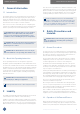

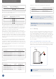
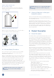
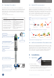
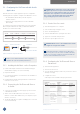
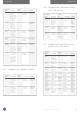
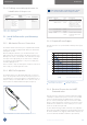
Table Of Contents
- 1 General Information
- 2 Liability
- 3 Safety Precautions and Hazards
- 4 Product Description
- 5 Installation
- 5.1 Unpacking
- 5.2 Configuring the VisiFerm mA with ArcAir Application
- 5.2.1 Installing ArcAir Basic on the Computer
- 5.2.2 Connecting the VisiFerm mA Sensor to ArcAir
- 5.2.3 Create User Accounts
- 5.2.4 Configuring the VisiFerm mA Sensor Parameters
- 5.2.5 Configuring the calibration settings
- 5.2.6 Configuring the temperature settings of SIP / CIP process
- 5.2.7 Configuring the analog interface for your process control system
- 5.2.8 Defining a measuring point name for identification of the process
- 5.3 Install VisiFerm mA in your Measuring Loop
- 6 Operation
- 7 Maintenance
- 8 Troubleshooting
- 9 Disposal
- 10 Bluetooth Certification
- 11 Ordering Information

19Operating Instructions VisiFerm
™
mA Sensors
INSTALLATIONINSTALLATION
NOTE: Shaft potential is isolated from the 4-20 mA
+ and – connection. Max isolation voltage is 500 V.
M12 PIN Function Color Description
3 HART/4-20 mA + Blue 4-20 mA two-wire interface,
functions as a current sink.
2 HART/4-20 mA – White If there is no resistor in the
HART Interface Card
integrated, an external
250 Ω resistor is essential
for HART communication.
4 not connected Black –
1 not connected Brown –
Housing Shield Green/ Connected to the housing
Yellow including the M12 female
connector.
5.3.3 Required Power Supply
VisiFerm mA sensors are specified with a minimal power supply
as follows:
Tested with 5m M12 sensor cable.
20
18
16
14
12
10
8
6
4
2
0
3.6 8 12 16 20 22
U [V]
I [mA]
Out of Operating Area
Figure 8: Minimal power supply as function of the output current.
Without HART communication
With HART communication
5.3.4 Electrical Connection for HART
Communication
VisiFerm mA sensor supports the platform-independent HART
7 and higher communication protocol. In most cases a HART
resistor is already installed in the HART Interface Card of the
process control system (Figure 9 A). If no resistor in the HART
interface card is integrated, an external 250 Ω resistor has to be
installed in series between the sensor and the process control
system as described on Figure 9 B.
For more details about the HART commands and configuration
please refer to the HART
®
Field Device Specification Ref 111001055
document available on the webpage www.hamiltoncompany.com
(search for VisiFerm mA HART
®
Field Device Specification).
5.2.8 Defining a measuring point name for
identification of the process
Parameter Default
Name Value Settings Location Descriptions
Measuring User can 10070760 Optional Information /
point define a XXXXYYYY* Info
sensor name Userspace
for better
identification
of the mea-
suring point
* XXXX = Sensor Information (Chapter 10)
YYYY = Sensor Serial Number
5.3 Install VisiFerm mA in your Measuring
Loop
5.3.1 Mechanical Process Connection
The VisiFerm mA mechanical design is compatible with all Hamil-
ton process housings, including Flexifits, Retractexs, Retractofits
and Hygienic Sockets.
Before installing the armatures, you should test that the seal is
tight and the parts are all in working order. Ensure that there is no
damage to the sensor or the armature. Check whether all O-rings
are in place in the appropriate grooves and are free of damage.
To avoid any mechanical damage to O-rings on assembly, they
should be slightly greased.
Please note that O-rings are wetted parts and greasy compounds
must comply to your FDA application needs.
5.3.2 M12 Pin Designation
The VisiFerm mA sensor is fitted with a M12 male, A coded con-
nector. The four golden contacts are denoted as pin 1 to pin 4. For
easy identification of each pin the M12 has a mark between pin 1
and pin 2. Always use Hamilton M12 sensor cables for safe con-
nection, which are available in different lengths (Chapter 10).
3
2
4
1
Housing
Figure 7: Requirements for electrical connection of VisiFerm mA sensors