
Operating Instructions
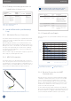


Table Of Contents
- 1 General Information
- 2 Liability
- 3 Safety Precautions and Hazards
- 4 Product Description
- 5 Installation
- 5.1 Unpacking
- 5.2 Configuring the VisiFerm mA with ArcAir Application
- 5.2.1 Installing ArcAir Basic on the Computer
- 5.2.2 Connecting the VisiFerm mA Sensor to ArcAir
- 5.2.3 Create User Accounts
- 5.2.4 Configuring the VisiFerm mA Sensor Parameters
- 5.2.5 Configuring the calibration settings
- 5.2.6 Configuring the temperature settings of SIP / CIP process
- 5.2.7 Configuring the analog interface for your process control system
- 5.2.8 Defining a measuring point name for identification of the process
- 5.3 Install VisiFerm mA in your Measuring Loop
- 6 Operation
- 7 Maintenance
- 8 Troubleshooting
- 9 Disposal
- 10 Bluetooth Certification
- 11 Ordering Information

21Operating Instructions VisiFerm
™
mA Sensors
OPERATIONINSTALLATION
The Device Description or DD can be downloaded on the HART
Communication Foundation webpage www.hartcomm.org
(search for Device Descriptions / DD Library) or on the Hamilton
webpage www.hamiltoncompany.com.
A
Sensor PCS (with HART Interface)
M12 Pin 3
M12 Pin 2
Field Device
4–20 mA
+24 VDC
0 VDC; Ground
HART resistor 250 Ω
A HART resistor is available in the HART interface card.
B
Sensor PCS
M12 Pin 3
M12 Pin 2
Field Device
4–20 mA
+24 VDC
0 VDC; Ground
HART resistor
250 Ω
A HART resistor is required in series between the sensor and the
process control system.
Figure 9: Wiring diagram for integration in the process control system
5.3.5 Electrical Connection for Analog
4-20mA Communication
The 4–20 mA interface enables direct connection of the Visi-
Ferm mA sensor to a data recorder, indicator, control unit or
PCS with analog I/O. The VisiFerm mA works as a current sink
sensor and is passive. Connect the sensor according to the pin
designations (Chapter 5.3.2). The 4–20 mA interface of the Visi-
Ferm mA sensors is pre-configured with default values for the
4-20 mA range, and measurement unit. Configure the 4.20 mA
interface according to your requirements for proper measure-
ment (Chapter 5.2.4).
Sensor PCS (Remote – I/O active)
M12 Pin 3
M12 Pin 2
4–20 mA
4–20 mA
4-20 mA / +24 VDC
4-20 mA / 0 VDC; Ground
Sensor PCS (Remote – I/O passive)
M12 Pin 3
M12 Pin 2
4–20 mA
4–20 mA
+ 4-20 mA
– 4-20 mA (GND)
External Power Supply
0 VDC;
+24 VDC
A
B
Figure 10: Two- wire loop wiring diagram for the 4-20 mA interface.
A: with an active current input card. B: with a passive current input card.
NOTE: If the current input card GND is internally
connected to GND of the Power Supply you do not have
to connect both GNDs externally.
6 Operation
ATTENTION! Only use the sensor within the speci-
fications (www.hamiltoncompany.com). Failure to do
so may lead to damages or measurement failure.
1) Remove the protective caps from the VisiFerm mA shaft,
and from the M12 sensor head
2) Mount the O-ring on the sensor shaft and screw the
ODO Cap firmly
3) Verify the functionality of the sensor including the ODO
cap (Chapter 7.1)
4) Scan the barcode on the ODO Cap label with the ArcAir
mobile barcode scanner or enter manually the information in
the sensor/ Sensor Information.
5) Calibrate the sensor (Chapter 7.3)
6) Connect the sensor to the process control system (Chapter 5)
7) Verify the measurement in air on your control system
8) Mount the sensor to the armature or process connection
(Chapter 5.3)