Buhl Industries VP-30 Visual Presenter USER MANUAL Version 8-5-08
NOTICES: PLEASE READ CAREFULLY BEFORE USE Use the visual presenter under rated electric conditions with included power supply only Do not place the visual presenter on any unstable surface. Do not place this device directly under sunlight or near heaters. Do not place this device near water. Keep the camera away from acid or alkali gas. Do not place this visual presenter in humid, dusty, windy or vibrant locations.
CONTENTS System Diagram: ....................................................................... 1 Rear Panel Connections ............................................................ 1 Front Control Panel ................................................................... 2 Specifications ............................................................................ 4 Initial Setup ............................................................................... 5 Operating Instructions .......................
System Diagram: 1. Camera head 6. Lighting arm 2. Remotes Sensor 7. Power switch 3. Upper mechanical arm 8. Base light 4. Main mechanical arm 9. Control panel 5. Side lamp 10.
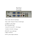
Rear Panel Connections Video, Audio: Video & Audio Input Video, Audio: Composite Video & Audio Output S-VIDEO: S-video Output MIC: Microphone Input VGA OUT1;VGA OUT2:VGA Output VGA IN1; VGA IN2: VGA Input PC IN: PC stereo audio input USB: PC connector DC12V: power adapter connector
Front Control Panel: 1) POWER: Press the Power button for 3 seconds to turn the camera on or off. 2) VGA: Switch between VGA output 1 & VGA output 2 3) RED+, RED-: Image chroma control (red). 4) BLUE+, BLUE-: Image chroma control (blue). 5) BRT+, BRT-: Image brightness control. 6) MIRROR: Toggle mirror image of camera output (Left to right) 7) LIGHT: Lamp control – Toggles between base lamp, arm lamps, all lamps and off. P/N: Switch the image mode between positive and negative.
SPECIFICATIONS: Power supply Maximum power consumption Operating condition 12V DC power adapter 20 W Temperature 0 — 45℃ Humidity 5% - 75% Non-condensing Dimentions(packing case) 425mm*477mm*170mm (W Weight 6.0 kg Light source Compliance Audio LED ROHS,CE,CCC,ISO9001 Inputs Video 1 x,<1.0 Vp -- p/75Ω Signal system NTSC VGA(PC) 2x Audio 1 x,<2 Vp -- p Video 1 x,<1.0Vp -- p/75Ω Outputs Signal system USB connector Camera 1 x,<2.
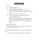
Initial Setup: 1. Unpack system and put aside all packing materials. Unfold the lighting arms until reach the end position. 2. Raise the main camera arm until it locks in place, then rotate the upper camera arm. 3. Rotate the camera head until the lens face the center of the base unit. 4. Connect RGB interface: use the provided RGB cable, connect the output of the visual presenter with the RGB input the display (monitor, television or projector). 5.
Operating Instructions 1. General: 1). Turn on the Power switch. 2). Place the target object on the stage. 3). Adjust the image size according to the object size by pressing the ZOOM up/ ZOOM down buttons on the control panel. 4). Press the “Focus” button for automatic focus. 5). “Freeze” button can be used to lock the image while changing displaying materials. 6) “Browse” and “Freeze” buttons can be used to compare a previous captured image with the current image side by side.
Troubleshooting Symptoms No image Possible causes/counter-measures 1. Power cord is not properly connected. 2. Cables are not properly connected. 3. Power switch is not turned on. 4. The built-in fuse is broken: Change fuse. Upper light not 1. The filament is broken. Change the bulb. on 2. the lamp is not fully plugged in its holder: Out of focus or 1. The object is too close to the lens. blurring image 2. Focus is on the max. point of “Tele” press “Wide”. 3. Auto-focus is not on: press AF again. 4.
PACKING LIST AND ACCESSORIES: Item Power cord VGA Cable User Manual Spare Fuse USB Cable Quantity 1 1 1 1(installed in the power receptacle) 1 Service and Support: Manufacturer’s Website: www.HamiltonElectronics.com Technical Support: support@hamiltonelectronics.