User Manual HFG2.0 Gas Fuel Metering Valve SD-6009 Rev.
This manual provides installation, maintenance, and operating instructions for the HFG2.0 Gas Fuel Metering Valve. Every attempt has been made to provide sufficient information in this manual for the proper operation and preventive maintenance of the valve. Read this manual in its entirety to fully understand the system. Operating the HFG2.0 Gas Fuel Metering Valve in accordance with instructions herein ensures long term and reliable operation.
TABLE OF CONTENTS Purpose of This Guide ................................................................................................................................... iii Product Identification...................................................................................................................................... iii What the User Should Know ......................................................................................................................... iv Related Publications....
Figure 1-11. Typical Power Connection With Battery.......................................................15 Figure 1-12: HFG2.0 System Signal Wiring Diagram......................................................19 Figure 1-13. Typical Analog Input Connection..................................................................20 Figure 1-14. Typical Analog Output Connection...............................................................20 Figure 1-15. Typical Discrete Input Command Connection ....................
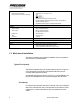
Purpose of This Guide This publication is designed to help the user install, operate, maintain and troubleshoot the HFG2.0 Gas Fuel Metering Valve. Product Identification Most of the information in this manual is applicable to all generations of the product.
What the User Should Know To install, operate and troubleshoot the HFG2.0, it is necessary for the user to have a fundamental understanding of: • Electronics concepts, such as voltage, current, and switches • Mechanical motion control concepts, such as inertia, torque, velocity, distance, force • ActWiz Software Operations Manual (p/n SD-6010) Related Publications iv HFG2.
1 INSTALLING THE HFG2.0 1.1 Before Beginning Inspection The HFG2.0 should be inspected immediately after unpacking. Check for dings or dents or any other obvious signs of damage. Remove the protective caps from the connectors and check for any bent pins or damage to the threads of the connectors. Examine the wires of the signal and power harnesses for any signs of damage to the wire insulation. In the event that any damage is detected, contact PECC for instructions about how to proceed.
Electrical Noise Guidelines PECC has taken the following measures to reduce electrical noise with the HFG2.0: • High-voltage wires are routed separately from low-level signals through the use of separate power and signal harnesses. An additional measure to reduce electrical noise is to: • Ensure that the HFG2.0 is properly grounded, as per Section 1.4 of this manual. Environmental Considerations The HFG2.
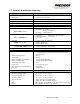
1.2 General Specification Summary PARAMETER VALUE Power Input Voltage Range 80-160 VDC; 120 VDC nominal Maximum Current 20 A Typical Transient Current +20A < 60ms; +10A < 120ms; -5A < 100ms Typical Continuous Current < 1A Inputs and Outputs Discrete Inputs ON Voltage: RUN and RESET commands OFF Voltage: 12 – 32 VDC, +24 VDC nominal @ 6.5 mA 1.0 VDC, maximum Discrete Outputs FAULT & OVERTEMP alarms OFF Voltage: Effective ON Resistance @ ≥ 1.5 VDC: 32 VDC maximum @ 150 µA typical 1.
Certifications North American Certifications CSA Class I, Div 1, Group B, C, D; T4 European Directive Compliance (CE Mark) EEx d, IIB+H2; T4 97/23/EC Pressure Equipment Directive (PED) 94/9/EC Potentially Explosive Atmospheres (ATEX) 02ATEX6051X 98/37/EC Machinery Directive 89/336/EEC Electromagnetic Compatibility Directive (EMC) Materials Actuator Housing 6061-T6 Anodized Aluminum Valve Housing 6061-T6 Anodized Aluminum 316 Stainless Steel (Optional) Conduit Union Zinc Plated Steel Seals Viton and
Figure 1-1. Typical HFG2.0 Gas Fuel System Installation Figure 1-2. Alternate HFG2.0 Gas Fuel System Installation Dimensions Figure 1-3 and Figure 1-4 show external dimensions for the 3-piece housing and 1-piece housing versions of the HFG2.0, respectively. Mounting Considerations The HFG2.0 can be mounted directly to a gas turbine engine skid using brackets provided by the engine manufacturer. The HFG2.0 can be mounted with any directional orientation, whether horizontal, vertical, or at an angle.
The HFG2.0 includes four (4) 0.50-24 UNC-2B mounting holes with stainless steel heli-coil inserts for securing the valve body. The mounting holes on the standard version of the HFG2.0 are located on the opposite side from the electrical connectors. The mounting holes on the reversed version of the HFG2.0 are located on the same side as the electrical connectors (see Figure 1-5). Figure 1-6 shows mounting provisions for the 3-piece housing version of the HFG2.0.
WARNING Explosion Hazard – Do not remove the clevis. Removing the clevis violates the warranty. Care should also be taken when rotating the clevis or indexing the screw pattern to avoid scratching the flame path or introducing particulates to the assembly. Pipe Connections The standard pipe connection for the HFG2.0 is per SAE J518, -32 (2 inch), code 61. The valve bodies contain locking helical inserts. Contact Precision Engine Controls for other connection options.
Vent Port The gas leakage rate through the vent port is less than 200 cm3/hr (air or N2 as test flow). The vent port features a 1/8-NPT fitting. See Figure 1-4. Consult local installation codes to determine whether and how to connect this port. Figure 1-3. HFG2.0 Dimensions, 3-Piece Housing 8 HFG2.
Figure 1-4. HFG2.0 Dimensions, 1-Piece Housing INSTALLING THE HFG2.
Figure 1-5. HFG2.0 Mounting Orientations 10 HFG2.
Figure 1-6. HFG2.0 Mounting Provisions, 3-Piece Housing (Standard Mounting Orientation Shown) INSTALLING THE HFG2.
Figure 1-7. HFG2.0 Mounting Provisions, 1-Piece Housing (Standard Mounting Orientation Shown) 12 HFG2.
Figure 1-8. HFG2.0 Mounting Provisions, 1-Piece Housing (Reversed Mounting Orientation Shown) INSTALLING THE HFG2.
1.4 Electrical Connections The HFG2.0 is suitable for use in hazardous locations. See the General Specification Summary in Section 1.2 for certifications. Ensure compliance with the factory recommendations, and that wiring is in accordance with local requirements. WARNING: 94/9/EC (ATEX) Compliance – Special Conditions for Safe Use: Two special factory-sealed unions are mounted on the equipment to ensure the electrical connection to the network and to provide the feedback signal to the user.
Figure 1-9: HFG2.0 System Power Wiring Diagram Figure 1-10. Typical Power Connection With Power Supply Figure 1-11. Typical Power Connection With Battery WARNING - Shock Hazard Connect both the 120 VDC power and auxiliary wires. If only the primary power wires are connected, the 120 VDC auxiliary power wires are electrically live and must be insulated on the ends. INSTALLING THE HFG2.
Note: A battery system is recommended for highest reliability. Note: If a 120 VDC power supply is used rather than a battery, ensure an output capacitance of at least 12,000 µF, which can both sink and source electric current. See Power Supply Requirements (Table 1-2). Note: Use a separate conduit for the power wiring. This prevents noise pickup and transmission from ancillary equipment, which could cause instability in the actuator.
Therefore, it is not possible to correctly state a single capacitance value that should be placed on the bus. It may require no added bus capacitance or hundreds of thousands of microfarads of capacitance. A typical output capacitance value used for non-battery power systems is 50,000uF, but the actual value depends on the specific power system as discussed above.
Signal Connections Signals are sent between the HFG2.0 and the user’s controller through the integral 17-wire signal harness. See Table 1-4 for the wire list for this harness. See Figure 1-12 for the system signal wiring diagram.
Figure 1-12: HFG2.0 System Signal Wiring Diagram Note: For proper operation of the controller, the voltage between the control inputs and the negative terminal of the power supply should be below 200 VDC. Note: The Serial Return is internally connected to the 120 VDC input Return. INSTALLING THE HFG2.
Analog Inputs The analog input, DEMAND, has a current range of 4 - 20 mA. It is electrically isolated up to 500 VAC from the enclosure, 120 VDC power, digital I/O, and serial interface. The analog interfaces are not isolated from each other. See Figure 1-13 for a typical analog input connection. CONTROLLER 4-20 mA OUTPUT HFG2.0 4-20 mA INPUT DEMAND [BRN] DEMAND RT N [WHT/BRN] + - 200Ω + - Figure 1-13.
Discrete Outputs The discrete outputs are +24 VDC. They are electrically isolated up to 500 VAC. See Figure 1-16 for a typical discrete output alarm connection. CONTROLLER DISCR ETE INPUT HFG2.0 DISCRETE OUTPUT CONTROLLER DISCRETE INPUT FAULT ALARM OVERTEMP ALARM [ORN] [BLK] FAULT RTN OVERTEMP RTN [WH T/ORN] [WH T/BLK] HFG2.0 DISCRETE OUTPUT FAULT RTN [WHT/ORN] OVERTEMP ALARM RTN [WHT/BLK] FAULT ALARM OVERTEMP ALARM [ORN] [BLK] Figure 1-16.
FUNCTION Standard 9-Pin COM Port Standard 25-Pin COM Port Transmit (Tx). Pin 3 Pin 2 Receive (Rx) Pin 2 Pin 3 Ground (GND) Pin 5 Pin 7 Table 1-5. Computer COM Port Pin Outs WARNING Property Damage Hazard – The serial inputs are not electrically isolated . Failure to properly isolate the user serial interface could result in actuator or computer damage. Use separate conduits for power and signal wiring. Close proximity to power lines may cause signal interference.
Recommended Wiring for System Signals The recommended wiring is a 17-conductor shielded cable containing twisted-pair wires with individual shields. Use a wire size large enough to accommodate the installation and provide a maximum fifty (50) ohm loop resistance. See Table 1-6 for recommended wire sizes. DISTANCE TO USER’S CONTROLLER RECOMMENDED WIRE SIZE (Minimum) ≤ 1000 ft. AWG 18, stranded > 1000 ft. Consult Factory Table 1-6. Wire Size for HFG2.
INTENTIONALLY BLANK 24 HFG2.
2 UNDERSTANDING THE HFG2.0 2.1 System Description The HFG2.0 is an electrically operated gas fuel-metering valve that requires only 120 VDC power, an analog fuel demand signal, and a discrete RUN command to achieve basic operational capability. No pneumatic or hydraulic power is required. The HFG2.0 is a closed loop servo system containing Motor Control Electronics (MCE), a brushless DC-motor-driven ball screw actuator and valve flow body assembly.
2.2 Electrical Description The electric actuator in the HFG2.0 incorporates digital motor control electronics (MCE). The MCE contain analog to digital converters, a digital signal processor (DSP), application specific integrated circuit (ASIC) and power supplies. Figure 2-1 shows the system block diagram. The MCE provides the interface for the user’s engine control system and power supply. The MCE incorporates analog and discrete inputs and outputs, and a serial interface.
during the RESET command. To reset the HFG2.0, +24 VDC must be applied across the RESET wires for at least 0.5 seconds in order to reset the controller and actuator. DEMAND Signal The DEMAND signal is a user-provided analog input that is used to control the position of the valve. The current level of the DEMAND signal is correlated to the position of the valve within its range. The minimum Demand signal of 4.0 mA is correlated to the CLOSED (Home) position.
Figure 2-1. HFG2.0 Electronics System Block Diagram 28 HFG2.
Alarms The HFG2.0 provides two two-wire alarm signals via the integral 17-wire signal harness. The discrete alarm outputs are solid-state switches which are normally closed. The user’s controller provides +24 VDC to complete the circuit. Refer to Figure 1-16 for typical connections. Refer to the General Specification Summary Table in Section 1.2 for alarm specification values. See Section 3.7 for additional details about alarms.
Note: The MCE analog and discrete signal interfaces are electrically isolated. The serial communication interface is optically isolated 2.3 Mechanical Description The HFG2.0 consists of two main parts, an actuator and a valve assembly. Actuator The actuator is the primary drive mechanism for the valve assembly. The actuator portion of the HFG2.
monitor winding temperatures. The motor electrical power and thermistor wires pass through a conduit into the electronics housing. Motor Rotor The motor rotor is locked to the ball screw shaft via a straight key. The motor rotor contains powerful magnets that align with the energized stator windings, thereby creating torque and shaft rotation. Resolver Assembly A brushless, non-contacting resolver is the primary HFG2.0 feedback sensor. Resolver excitation is achieved via a sinusoidal signal from the MCE.
Extension Rod and Bearings The extension rod is threaded on the ball nut. As the ball nut translates, the extension rod moves in and out of the HFG2.0 main housing. Counter-clockwise (CCW) rotation (facing the motor end of the actuator) of the motor rotor and screw shaft results in the extension rod extending out of the main housing. Clockwise (CW) rotation results in the extension rod retracting back into the main housing. The extension rod support bearing is provided for lateral support.
Orifice Assembly The orifice assembly contains a set of poppets and orifice plates. Fuel flow is metered between the INLET port chamber and OUTLET port chamber in proportion to the poppet position and resultant flow area. The poppet assembly is connected to the extension rod of the actuator. As the actuator retracts, the poppet assembly retracts to increase the flow area between the poppets and the two orifices.
Figure 2-2. HFG2.0 Cut-Away View – Actuator Main Housing Assembly 34 HFG2.
Figure 2-3. HFG2.0 Cut-Away View (Partial) CH. 2: UNDERSTANDING THE HFG2.
2.4 Identification Plate A product identification plate is attached to the HFG2.0 housing assembly. Figure 2-4 shows a typical identification plate. The identification plate lists model designation, product part number, revision and unit serial number. Hazardous area operation, certification and electrical wiring interface information is also provided. When a unit is refurbished by PECC, a product refurbishment plate is also attached to the HFG2.0 housing assembly.
Figure 2-5. Typical Refurbishment Plate CH. 2: UNDERSTANDING THE HFG2.
INTENTIONALLY BLANK 38 HFG2.
3 OPERATING THE HFG2.0 This section refers to the position of the actuator when describing operation of the HFG2.0 valve. The end of the actuator extension rod is connected to the poppet assembly of the valve. The linear motion of the actuator, both extension and retraction, is directly translated to the poppet assembly. The position of the actuator correlates directly to the position of the valve poppets relative to the orifices.
this point, the HFG2.0 has no information about the position of the actuator extension shaft. When the HFG2.0 receives the RUN command, it will initiate motion in the homing direction. The default homing direction for the HFG2.0 is “Extend”. This means that the first movement after Power Up or Reset will be an extension of the actuator in the HFG2.0. The actuator will extend at the rate specified by the Homing Velocity in the Set Up parameters (default is 0.5 in/sec) until a mechanical stop is encountered.
Figure 3-1. HFG2.0 Basic Operation Flow Chart CH. 3: OPERATING THE HFG2.
3.4 Moving to Stop Position The Stop position is a fail-safe position that may be set anywhere between Home (zero position, Valve Closed) and maximum span (maximum flow). The default value for Stop position is 0.0 inches, as defined in the Set-Up parameters. The actuator will move to the Stop position if the DEMAND signal is ≤ 2 mA (signal loss) at any time after the actuator has completed Homing. It will also move to the Stop position if the RUN command is removed during any of the running modes.
Full Span Position (Maximum Flow) The Full Span (Maximum Flow) position correlates to a DEMAND signal of 20 mA. The maximum Span possible for the HFG2.0 is 1.0 inches due to the configuration of the valve assembly. The maximum Span possible for the actuator used in the HFG2.0 is 2.0 inches due to its mechanical configuration. The Span value in the Set-Up parameters has a default setting of 1.
A non-linear interpolation table can be created to define positioning at 16 discrete current levels in the DEMAND signal range, but only during Set Up using the ActWiz Software. See the Section 3.8 for additional details about Set Up parameters. Figure 3-3. Dead Band of Actuator, Position vs. DEMAND Curve 3.6 Resetting the Actuator To reset the HFG2.0, +24 VDC must be applied across the RESET wires for at least 0.5 seconds. The leading edge of the RESET command causes the HFG2.
3.7 Monitoring System Health The firmware program continuously monitors system health while the HFG2.0 is powered. If any of the health parameters are out of the normal operating range, the MCE outputs a discrete fault alarm to the user’s controller. Some fault causes are: • MCE over-current • Tracking error • RDC failure • Input voltage out of range Fault Alarms The HFG2.0 features two discrete, non-latching outputs that are configured as fault alarms.
See Table 3-4 for a list of Over Temp conditions represented by the of the HFG. OVERTEMP alarm in earlier generations Fault File The HFG2.0 firmware also captures the fault data in the EEPROM. If the HFG2.0 is operational, a fault file can be downloaded using ActWiz software via the RS232 interface. The fault file will provide fault information and possible causes. The HFG2.0 must be in the Power Up / Set Up state to download the fault file. See Section 3.8 for details about the Power Up / Set Up state.
Fault Type Low Alarm High Alarm Fault Enable Persist Time Auto Reset Output Driver Overcurrent N/A 1000 lbf Yes 10 Sec Yes Yes Tracking Error N/A 3.33 % Yes 10 Sec Yes Yes Position Demand 3.5 mA 20.5 mA No 1 Sec No No RDC Failure N/A N/A Yes N/A No Yes +14 Volts 12.0 Volts 16.0 Volts Yes 7.5 Sec Yes Yes –14 Volts –16.0 Volts –12.0 Volts Yes 7.5 Sec Yes Yes Input Voltage 75.0 Volts 180.0 Volts Yes 7.
Fault Alarm Type Driver Over Current Persist Time 10 Sec 1 Sec Fault Action Driver current > Max Force equivalent current, Fault. Driver current > Max Force equivalent current, Fault. If persists for 1 Min., Shutdown Driver current > 18 Amps, Fault. If persists for 1 Min., Shutdown 10 Sec Tracking Error If in RUN state, not in home dead band and position error > allowable, Fault. If not in overcurrent, RDC not faulted and feedback not equal to demand, Fault.
Fault Type Motor Persist Time 10 Sec Fault Action . If fault exists and Motor temp > 130° C, Fault. Motor temp > 135° C for 10 Sec, shutdown. 1 Sec Motor temp > 130° C, Fault . If fault exists and Motor temp > 130° C for 60 Sec, shutdown. Electronics 10 Sec Electronics temp > 110° C, Fault. 1 Sec If fault exists and Electronics temp > 115° C for 10 Sec, shutdown. Electronics temp > 110° C, Fault. If fault exists and Electronics temp > 100° C for 15 Sec, shutdown. Table 3-4.
3.8 Changing Set-Up Parameters The HFG2.0 uses a number of variables to define its functionality. These variables are called Set-Up parameters and they are stored in the EEPROM in the HFG2.0. Default values for these variables are loaded into the EEPROM at the PECC factory. The Set-Up parameters are reloaded into the system registers each time the HFG2.0 is powered up or reset. See Table 3-5 for typical Set-Up parameters. Users can change the Set-Up parameters to better suit their specific applications.
PARAMETER DESCRIPTION FACTORY SETTING Part Number Describes part number of actuator model Per Drawing Actuator Type Describes type of actuator Stand Alone Command Source Sets type of command signal Analog Home Controls the direction the actuator will move, extending or retracting, to find the mechanical stop (HOME) Extend Span Sets the maximum stroke length, measured from the HOME position 1.0 inches Stop Position Sets the signal loss position, measured from the HOME position 0.
INTENTIONALLY BLANK 52 HFG2.
4 MAINTAINING THE HFG2.0 Under normal operation, the HFG2.0 requires no formal maintenance program.
INTENTIONALLY BLANK 54 HFG2.
5 TROUBLESHOOTING This section provides troubleshooting information for the HFG2.0. You can isolate most electrical faults by using an external oscilloscope and digital voltmeter (DVM) and computer with diagnostic software. The HFG2.0 is comprised of highly reliable components and should not develop service problems under normal operating conditions. However, over a period of time and service, failures may develop.
Symptom Probable Causes Corrective Action Valve Inoperative FAULT alarm Power Wires not connected Ensure RED and GREEN wires correctly connected to valve Ensure 120 VDC Primary System Power at valve No or low 120 VDC power Valve Inoperative NO FAULT alarm No RUN or position command Ensure VIOLET and WHITE/VIOLET wires correctly connected to valve Ensure 24 VDC RUN and position command at valve Actuator moves toward HOME then stops Intermittent RUN command Ensure consistent 24 VDC RUN command and
Symptom Probable Causes Corrective Action RS232 Interface Inoperative Incorrect wiring Ensure WHITE/ORANGE/YELLOW, WHITE/ORANGE/BLUE, WHITE/ORANGE/GREEN wires correctly connected to valve and laptop PC. No or low 120 VDC power COM1 not connected RESET or RUN command is ON Ensure 120 VDC Primary System Power at Valve Check laptop/PC com port Remove RESET or RUN command Table 5-1.
Function Actuator Wire Colors Resistance Value DEMAND BRN and WHT/BRN 225Ω RUN VIO and WHT/VIO 4.7 KΩ RESET GRY and WHT/GRY 4.7 KΩ POWER RED and GREEN High Impedance, but not open circuit. MOTOR CURRENT BLU and WHT/BLU High Impedance POSITION YEL and WHT/YEL High Impedance FAULT Alarm ORN and WHT/ORN High Impedance OVERTEMP Alarm BLK and WHT/BLK High Impedance Table 5-3. HFG2.0 Electrical Continuity Troubleshooting Chart 58 HFG2.
5.1 FAULT File The FAULT and OVERTEMP alarms are discrete outputs from the HFG2.0. The FAULT and OVERTEMP alarm circuits are closed in the normal operating condition. If the HFG2.0 detects a fault, the alarm circuit for that fault opens, and the user-provided controller should detect the open circuit. The fault is recorded in the fault file. The HFG2.0 firmware captures the fault data in the EEPROM. If the HFG2.0 is operational, a fault file can be downloaded using ActWiz software via the RS232 interface.
Watchdog expired The MCE watchdog timer continuously monitors the firmware program. Should the MCE firmware program stop functioning, or attempt to access an illegal address, the MCE signals a fault. This fault does not clear without RESET command. Resolver to Digital Converter (RDC) failure The MCE contains a resolver to digital converter chip (RDC) that provides position feedback information to the DSP. The RDC chip has on-board health monitoring.
APPENDIX A: DECOMMISSIONING & DISPOSAL This section contains recommended HFG2.0 decommissioning and disposal practices. It is for permanent removal or replacement of the installed product, with no intentions of rework, overhaul, or to be used as spares. For removal follow proper lockout /tagout procedures and verify no live electrical circuits: • Disconnect the 4 wires of the integral power harness to the HFG2.0. • Disconnect the 17 wires of the integral signal harness to the HFG2.
INTENTIONALLY BLANK 62 HFG2.
APPENDIX B: GLOSSARY Term Definition RUN Command A discrete 24 VDC signal that enables the HFG2.0 actuator and valve to move. RESET Command A discrete 24 VDC signal that causes the HFG2.0 internal program (firmware) to jump to the beginning. Controller A user-provided computer that executes commands to the HFG2.0 and accepts analog and discrete feedback.
INTENTIONALLY BLANK 64 HFG2.