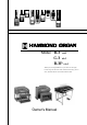
*# 1 14)#0 Model $ OM % OM $ 2 OM Thank you, and congratulations on your choice of this organ. In order to get the most out of this instrument for many years to come, first take the time to read this manual in full.
IMPORTANT SAFETY INSTRUCTIONS Protect the power cord from being walked on or pinched, particularly at plugs, convenience receptacles, and the point where they exit from the apparatus. Read these instructions. Keep these instructions. Only use attachments/accessories specified by the manufacturer. Heed all warnings. Use only with the cart, stand, tripod, bracket, or table specified by the manufacturer, or sold with the apparatus.
FOR UNITED KINGDOM: FOR YOUR SAFETY, PLEASE READ THE FOLLOWING TEXT CAREFULLY This appliance is supplied with a molded 3-pin mains plug for your safety and convenience. The plug contains a 5 amp fuse. Should the fuse need to be replaced, please ensure that the replacement fuse has a rating of 5 amps and that it is approved by ASTA or BSI to BSI1362. Check for the ASTA mark or the BSI mark on the body of the fuse.
IMPORTANT - PLEASE READ The Hammond B-3 is the most popular organ evermade, and its sound is legendary. We have designed this model to be true and authentic to the exact vintage detail, as well as providing a large variety of modern features that allow greater flexibility no matter the musical style you wish to play. This Owner’s Manual is designed to explain the operating features of this Hammond organ as simply and graphically as possible.
BATTERY BACK UP This organ uses a battery-backed RAM to remember your changes to the Parameters. When the battery voltage becomes low, the Display will show: If you see these messages, you should immediately back up your parameter changes, if you have made any.
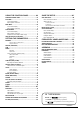
Table Of Contents IMPORTANT SAFETY INSTRUCTIONS ............................................ 2 IMPORTANT - PLEASE READ .......................................................... 4 BATTERY BACK UP ......................................................................... 5 Index .............................................................................................. 8 MAIN FEATURES ............................................................................ 9 HOW TO ASSEMBLE (B-3 mk2) ..................
USING THE CONTROL PANEL ............... 63 SAVE THE SETUP ................................. 107 OPERATION CONTROL PANEL ...................................................... 64 PLAY MODE .................................................................................. 65 SAVE YOUR SETUP .................................................................... 108 How to read the Display ...................................................................... 65 Button operation in this mode .................
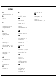
Index A L Adjust Presets 40, 95, 108 Leakage Noise 72 Leslie 41, 56, 84 B M Bank 37 Bend 39 Chorale 56 Combination Presets 58 CompactFlash 108 Custom Tone-Wheels 92 Main 23, 24 Manual Bass 42, 90 Master Tune 75 Menu Mode 66 MIDI 98 MIDI Pedalboard 33 Motor Control Switch 39, 91 D O Default 95 Display Lock 70 Drawbars 40, 48, 72 Overdrive 41, 55, 80 C E Echo 23, 24 Effect Loop 30 Equalizer 88, 57 Expression Pedal 39, 91 External Zones 100, 102 F Fold-Back 72 Foot Switch 39, 91 Footage 48 Funct
MAIN FEATURES 9 MULTI-CONTACT MANUALS The keyboards used in this organ have been totally redesigned and 100% faithfully replicates the “Direct Analog Keying System” used on the original B-3. TONE-WHEELS REBORN THROUGH DIGITAL TECHNOLOGY The “Digital Tone-Wheel System” replicates the Tone-Wheel wave-forms created by the mechanical system of the original B-3. The 96 wave-forms are always in oscillation just as in the original.
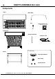
HOW TO ASSEMBLE (B-3 mk2) 10 Components Organ Music Rack Key CompactFlash Card (inserted into the organ) Pedalboard Hexagonal Wrench AC Power Cord Bench USA Only Leslie Speed Switch Wire Clamp Tapping Screws *# 1 $ OM % OM $ 2 OM Owner’s Manual
Connect the Pedalboard Attach the Leslie Speed Switch (USA only) HA HA 1. Place the Pedalboard on the floor in front of the organ. 2. Take the Pedal Cable out of the organ and insert the plug into the connector on the Pedalboard. 3. Hold the plug with the “Retention Hook” and lock it on by turning the screw knob. 4. Slide and push in the Pedalboard beneath the organ until it stops. 1. Locate a #2 Phillips Screw Driver. 2. Position the Leslie Speed Switch on the front left of the Great Manual.
Attach the MAIN/ECHO Switch Bench The space underneath the top board of the bench is provided for (optional) This switch is for selecting either of the Leslie speakers if 2 are connected. 1. Locate a #2 Phillips screw driver. 2. Position the Main/Echo Switch to the front left of the Great Manual. 3. Attach with the 4mm tapping screws from underneath. 4. Insert the plug of the Main/Echo Switch cable into the MAIN/ECHO Jack on the Volume Panel. storing scores, music rack, etc.
Manual Lid Put on the Music Rack Insert the Music Rack into the rail whenever necessary. 1. When you open the lid, hold and lift the front gently with both hands and fold it. 2. When you close the lid, hold the front of the folded lid with both hands and put down gently to close. ATTENTION Be careful not to pinch your fingers when you open or close the lid. If the player is a small child, be sure to help him/her to open or close the lid. ATTENTION Do not put excessive pressure on the music rack.
HOW TO ASSEMBLE (B-3P mk2) 14 Components Organ (closed view) Music Rack (inside of the lid) CompactFlash Card (inserted into the organ) Stand Hexagonal Wrench AC Power Cord Leslie Speed Switch, Spacer Expression Pedal Wire Clamp *# 1 $ OM % OM $ 2 OM Owner’s Manual
Mount the Organ on the Stand CAUTION The organ must be mounted on the stand by two persons using both hands. 1. Remove the Knob Bolts on both sides of the organ. 2. Unfold the stand and place it in the upright position. 3. The stand must be placed flat on the floor. Turn the adjusters, if necessary, to level the stand. 4. With a helper, lift the organ gripping the side handles, then carefully mount it on the stand.
Connect the Expression Pedal C o n n e c t t h e Pe d a l b o a r d (optional) Insert the plug the cable from the Expression Pedal to the EXP.PEDAL connector on the power panel (on the bottom of the organ), matching the direction, then tighten it by turning the ring on it. 1.
Attach the Leslie Speed Switch Attach the MAIN/ECHO Switch (optional) 1. Remove the 2 inside knob screws on the front left of the Great Manual. 1. Remove the 2 outside knob screws on the front left of the Great Manual. 2. Put the spacer on the plate of the Leslie Speed Switch. 2. Put the spacer on the plate of the Main/Echo switch. 3. Attach the Leslie Speed Switch on the organ with the knob screws. 4. Insert the plug of the Leslie Speed Switch cable to the LESLIE SWITCH jack on the volume panel.
Open the Manual Lid Install the Music Rack The Music Rack is inside the back of the manual lid. 1. Turn the knob screw inside the manual lid counter-clockwise and remove the stopper. 2. Slide the music rack into the music rail. 1. To open the manual lid, release the lock on both sides, then gently lift it holding the knobs on both sides bwith both hands. When the lid opened about 135 degrees, slide it back and off the hinge. 2. To close, hook the lid on the hinge and put it upright to 90 degrees.
Introduction
NAMES AND FUNCTIONS 20 Top View of the Organ 4 5 6 8 7 9 17 18 19 20 10 21 and Pedal Drawbars. SWITCH PLATE 1. POWER Switch This switch turns the power on and off. Even when the POWER switch is turned off, electricity is still flowing to the instrument at a minimum level. When you are not using the instrument for an extended time, make sure you unplug the power cord from the wall AC outlet. 2. MOTOR CONTROL Switch This is for changing the pitch while playing.
2 11 12 3 1 13 14 15 16 RIGHT TABLETS MANUALS 13. PERCUSSION Tablet This is for switching the Percussion on/off. 17. SWELL(Upper) Preset Keys These are for selecting the Presets of the Swell(Upper) Manual. 14. PERCUSSION VOLUME Tablet This is for switching the volume of Percussion: NORMAL/SOFT. 18. SWELL(Upper) Manual This is a manual with 61 notes, multi-contacts (for Drawbars & Percussion) with contacts (for MIDI OUT). 15.
Volume Panel 25. MASTER VOLUME Knob This is for controlling the total volume of this organ. 22 26 24 23 25 28 27 26. BASS Knob This is for increasing/decreasing the volume of the Bass frequencies. 29 22. MAIN/ECHO Jack This is for connecting the Main/Echo Switch MES-1. 23. HEADPHONE Jack This is for connecting Headphones. The external Leslie speaker is turned off, when a plug is inserted to this jack. 27. TREBLE Knob This is for increasing/decreasing the volume of the Treble frequencies. 28.
Accessory Panel (B-3 mk2, C-3 mk2) EFFECT LOOP 37 40. SEND Jack This is a post-internal effects patch-out point. 38 If a plug is inserted to this jack, signals inside the organ are cut off. (Rating Output Level: 1.23V +4dBm, Output Impedance: 600Ω) 40 41 39 42 43 41. RETURN Jack This is a post-internal effects patch-in point. This jack is used also as the input terminal to the rotary channel from an external sound source. (Rating Input Level: 1.
Accessory Panel (B-3P mk2) 48 47 50 51 49 52 When a plug is inserted to this jack, signals inside the organ are cut off. (Rating Output Level: 1.23V +4dBm, Output Impedance: 600Ω) 54 53 55 51. RETURN Jack This is a post-internal effects patch-in point. This jack is used also as the input terminal to the rotary channel from an external sound engine. (Rating Input Level: 1.23V +4dBm, Input Impedance: 10kΩ) MIDI TERMINAL SOUND INPUT TERMINAL 47.
PEDALS 59. EXPRESSION Pedal This is for changing the total volume of the organ. 59 B -3 mk2 The Foot Switch is attached on the bottom left. B -3P mk2 60. Pedalboard 25 notes. Radial flat type, non-velocity keyboard. 61. Foot Rest Rest your feet when you are not playing the Pedalboard.
*# 1 $ OM % OM $ 2 OM Owner’s Manual
HOOK-UP *# 1 $ OM % OM $ 2 OM Owner’s Manual
BASIC HOOK-UP 28 See the figure below for connection. This organ has no built-in speaker or amplifier. Before you connect a Leslie Speaker to the organ, be sure to turn OFF the power of the organ and the external equipment, if any is connected. The Leslie Speaker is connected to the LESLIE/MAIN jack on the organ using the exclusive 11-pin Leslie Cable attached to the speaker or the LC-11-7M (optional). Plug in the Leslie Cable to the jack, correctly matching the notches.
B-3P mk2 Fasten the cables using hook-and-loop fastners.
USING EFFECT LOOP 30 External effects may be used while a Leslie Speaker is connected to the organ using the Effect Loop. The effects unit should have the same input/output gain and corresponding with the rating level of +4dBm. NOTE: NOTE: The Effect Loop is inserted between the built-in Effect (Leslie, Reverb, etc.) and the Master Volume. If using the LINE OUT jack and the HEADPHONE jack, simultaneously the Effect Loop will only function on the R (right) side.
USING TWO LESLIE SPEAKERS Two Leslie Speakers may be connected to this organ. Connect the first Leslie Speaker to the MAIN socket and the second to the ECHO socket. The organ sounds are usually produced from both Leslie Speakers. If you connect the MAIN/ECHO switch, you can select which Leslie sounds while you are playing. 31 The sound that is input from LINE IN jack will be sent out to both Leslie speakers regardless of the position of the MAIN/ECHO switch.
USING NO LESLIE SPEAKER 32 If no Leslie Speaker is available, you can use the built-in Leslie Effect by means of the LINE OUT jack. If the Leslie Speaker and the LINE OUT jack are used together, the built-in Leslie Effect is heard only on the L channel. You may also use a traditional keyboard amp or PA system. USING HEADPHONES You can practice silently by connecting the stereo headphones to the HEADPHONE jack of this organ.
CONNECTING THE MIDI PEDALBOARD You may connect a MIDI Pedalboard, instead of the traditional Pedalboard. All the note information received at the MIDI PEDAL IN jack is output as the Pedal Part, regardless of the MIDI channel. The following MIDI pedalboards connectable to this organ are also available from us as optional accessories: XPK-100 (13 notes) XPK-200 (20 notes) NOTE: NOTE: 33 You can attach an expression pedal (provided with the B-3P mk2) on the XPK-200.
*# 1 $ OM % OM $ 2 OM Owner’s Manual
TURN ON AND PLAY *# 1 $ OM % OM $ 2 OM Owner’s Manual
POWER ON 36 How to power on After connecting your organ to the power outlet, please follow this procedure before switching on the power. To avoid possible damage to your speakers, please follow this procedure exactly. 1. Set the [MASTER VOLUME] Knob at minimum. 2. Switch on the power of any external effects devices. 3. Turn on the [POWER] switch of the organ. The pilot lamp will light up and the PLAY mode (fig.) is displayed, following the title.
USE OF PRESET KEYS The registrations (settings) of the Drawbars and other parameters may be recorded to the Preset Keys on the lefthand side of each manual. 37 The 4 Banks are loaded with a default library of Presets allowing you to play your organ immediately. There are 5 Banks with 11 Presets in each. The chart on the left outlines the Bank/Preset structure. The “Bank” is common for the entire organ, but the Preset Keys for the Swell and Great are independent of each other and are selected separately.
Play the Pedalboard The Pedal tones are controlled by the Pedal Drawbars which are in the center of the Drawbar row. Pull out the 16' Drawbar as shown at left to the full length. Play the Pedalboard. The Drawbar to the right of the 16' is the 8'. Pull that Drawbar out and play the Pedalboard (Explanations of the Drawbars and the “foot” names are included in the next section “Creating the Settings”). The Pedal Part settings were not called at the Preset Keys on the original B-3.
ADDING EXPRESSION TO YOUR PLAYING 39 Expression Pedal Unlike the piano, the organ does not get louder, the harder you play the keys. The organ’s volume is controlled by using the expression pedal. As you depress the pedal forward, the volume rises, and lowers when you return it. NOTE: You can adjust the curve of the expression pedal. (P. 91) Foot Switch The Foot Switch, on the left side of the Expression Pedal can be programmed for various functions.
TRY MAKING YOUR OWN SOUND 40 You will be able to produce your own sound by using the exclusive features of your HAMMOND ORGAN, such as Drawbars, Percussion, Vibrato/Chorus, Overdrive, and the Leslie effects. Let’s go through the first steps: Select the Preset Key [B] Select the Preset Key [B] first. The Presets Key [A<] and [B] are special Presets called “Adjust Presets”, directly connected with A< Drawbars and B Drawbars respectively.
Add Effects VIBRATO AND CHORUS “Vibrato and Chorus” slightly changes the Drawbar pitch and adds warmth to the sound. [SWELL] Tablet, [GREAT] Tablet Switches the Vibrato/Chorus on and off for each manual. [VIBRATO AND CHORUS MODE] Knob Controls the Vibrato and Chorus Depth. The degree of depth corresponds with the number. “V” adds Vibrato sound by changing the pitch, “C” adds the original shimmering Hammond chorus. NOTE: You can fine-adjust the speed etc. of the Vibrato&Chorus. (P.
PEDAL SUSTAIN The Pedal Part sound can be set to smoothly decay after the key is released. This is called “PEDAL SUSTAIN”. To use this “Pedal Sustain” function, refer to the control panel. 1. Press the [PLAY] button, and display “P. SUS” on the bottom right of the display. 2. Switch ON the PEDAL SUSTAIN using the [VALUE] button.
Recording Preset Keys You can record your Drawbar registrations in the Preset Keys. You can also freely change the preset data loaded as the factory default. To record Drawbar registrations in the Preset Keys, refer to the control panel. Ex. Memorize to “2-D” 1 1. Go to the PLAY mode. Press the [PLAY] button to go to the PLAY mode. 2 2. Go to the Record mode. Press the [RECORD] button and go to that mode. 3 3. Designate the Bank. Press the [PARAM] button and select the Bank to record.
4 4. Select the Part to record. Press the [PAGE] button and select either SWELL or GREAT to record the Preset. For this example select “GREAT”. NOTE: You can select the part to record by the Preset Key, as well. 5 5. Select the Preset Key. Select the Preset Key ([C<] - [A]) to record. For this example, Press [D]. 6. Commit the Preset. 6 Press [4] OK. The Preset is recorded and the following message appears on the display for a few seconds. Recording PRESET...
SETTING UP *# 1 $ OM % OM $ 2 OM Owner’s Manual
SOUND ENGINE STRUCTURE 46 System structure of this Organ *# 1 $ OM % OM $ 2 OM Owner’s Manual
See the illustrated System Structure of your organ on the left page. TONE-WHEELS The sound source or “engine” of Hammond Organ is the Virtual Tone-wheel. Generator. As on the original B-3, each of the 96 Virtual Tone-wheels are oscillating at a different pitch. There are NO moving parts inside this organ. KEYS The tones of the 96 Virtual Tone-wheels are switched at the keyboard with the “Direct Analog Keying System” exactly as on the original B-3.
HARMONIC DRAWBARS™ 48 The 9 Drawbars (plus 2 for the Pedal) on this organ are used to create the basic sounds. Each Drawbar is marked with the numbers 1 - 8. If you push back the Drawbar until you cannot see any number at all, the sound of the Drawbar is not heard. If you pull it out to the fullest position The sound level is maximum. No Volume Full Volume The pitch of each Drawbar is as shown above, when the middle C is depressed.
Drawbars for the Swell/Great Manuals Relation between the Preset Keys and the Drawbars The two sets of Drawbars on the left-hand side are for the Swell Manual and the two on the right-hand side are for the Great Manual. To actuate them, use the Preset Key [A<] or [B] respectively. When the other [C<] to [A] Preset Keys are selected, the Drawbar registrations are recalled inside the organ, and the tone that plays will not match the Drawbars physical settings.
Drawbar Registration Patterns The Drawbar Registration is matched by digits. It is easy to remember the typical combinations of the 9 Drawbars by their forms. The Drawbar Registrations are grouped into the following 4 patterns: Flute family (2 step pattern) Accompaniment Flute 8' I ....... 00 Accompaniment Flute 8' II ..... 00 Accompaniment Flute 8' III .... 00 Chorus of Flutes 16' ................ 80 Orchestral Flute 8' ................... 00 Piccolo 2' .................................
Modern Drawbar Registrations The Drawbar registrations introduced on the previous page are typically for classical music. They were created at the dawn of the Hammond Organ, when it was intended to sound like a pipe or church organ. Later on, as the Hammond Organ spread throughout Jazz, Pop, Rock and (especially) Gospel music, Some timeless registrations become common. Jazz Bluesey Groovy & Funky Max Power APPLICATION OF PERCUSSION When Percussion is used, the sound of the 1' Drawbar is cancelled.
Controlling the Registration while playing a Preset To temporarily modify the registration by operating Drawbars, while a Preset Key is selected between [C<] and [A], operate either [A<] or [B] holding down the [PLAY] button. In the registration, only the operated bar’s footage changes. For example, draw 1' of the Swell Drawbar [A<] or [B] holding down the [PLAY] button, if you want to add 1' while playing the Preset Key [G] of the Swell Manual.
PERCUSSION 53 The touch-response percussion adds a clear-cut “attack” to the organ sound. It is a Hammond exclusive. Percussion is usually combined with the Drawbar sound. [PERCUSSION] Tablet Turns on the Swell (Upper) manual percussion when swell Preset [B] is selected. When percussion is activated the 1' Drawbar does not sound. [PERCUSSION VOLUME] Tablet This is for controlling the Percussion volume.
VIBRATO AND CHORUS 54 VIBRATO adds warmth to the tone by slightly oscillating the Drawbar pitch. CHORUS adds richness to the sound by doubling the fundamental slightly detuned. [VIBRATO SWELL] Tablet This enables the Vibrato and Chorus effects on the Swell manual. [VIBRATO GREAT] Tablet This enables the Vibrato and Chorus effects on the Great manual. NOTE: You can choose to add Vibrato & Chorus effects on the Pedalboard. (P.
OVERDRIVE 55 The overdrive gives distortion to the sound by highly increasing the pre-amplifier input gain. The genuine tube circuitry allows a wide range of sound from unclipped warm and clean to a hard distorted overdrive, by varying the amount of the overdrive control. [OVERDRIVE] Knob This is for controlling the amount of overdrive of the tube amp circuit. Controls the distortion amount. Full left is “clean”. The overdrive effect increases an you rotate the knob. NOTE: You can fine-set the overdrive.
LESLIE 56 The Leslie Speaker produces its unique effect by utilizing rotors that give tremolo, vibrato and motion to the sound. The Leslie Speaker is controlled by the Leslie Speed Switch. If no Leslie Speaker is connected, this switch controls the built-in Leslie Effect. [CHORALE] Rotors will turn slowly, producing an effect suitable for use with hymns, classical style music and some slower songs. [STOP] Rotors do not turn. Animation can be provided by using Vibrato and Chorus.
EQUALIZER, REVERB 57 The Equalizer and the Reverb add a final touch to the tone. The Equalizer regulates the tonal quality. The Reverb adds the effect of playing in a concert hall. You control their basic functions on the panel under the left side of the keydesk. Equalizer [BASS] Knob BASS is assigned here at the time of shipment from the factory. This increases/decreases the bass sound. About ±9dB is adjustable at 100Hz. [TREBLE] Knob TONE is assigned here at the time of shipment from the factory.
PRESETS 58 You can record all the aforementioned settings to the Presets. In the factory default setting, only the Drawbar registrations are called as on vintage B-3’s. BANK and KEY There are 5 “BANKS” of presets, each containing 12 presets corresponding to the reverse keys to the left of each manual. The SWELL and GREAT presets are independent of each other, but the BANKS are common to both manuals. You may only select one BANK at a time. To select a “BANK”, press the [PARAM] button in the PLAY mode.
Using Plural Presets at the Same Time When pressing a Preset Key, the previously selected key is released. However, it does not mean you can not select more than one key. If you select more than one Preset Key at the same time, the registrations recorded for all those keys are mixed. Try this. If the other parameters than the registrations in the Preset Function Mode are contained in the preset, the contents of the key pressed last are called out.
Naming the BANK You can name each BANK. (The KEYs have no name.) 1 Go to MENU. Press the [MENU/EXIT] button. The [MENU] mode appears. 2 Go to the PRESET FUNCTION mode. Press the [4] PRESET button, and go to the PRESET FUNCTION mode. 3 Input the NAME. Up to 8 characters can be input. [P ARAM] button [PARAM] button: moves the cursor. [V AL UE] button [VAL ALUE] button: selects the letters. The characters available are signs, numerals, Capital and small letters.
VOLUME 61 The volume of this organ is controlled in three ways. [MASTER VOLUME] Knob This controls the total volume of this organ (except the sound input from the LINE IN jack). This is the same as a volume knob on an ordinary electronic musical instrument or audio equipment. Expression Pedal This is operated by foot. The volume increases as you fully depress the pedal. As you pull back the pedal, the volume decreases. As the volume is lowered, the tone becomes warmer as a side effect.
Tone-Wheels and Multi-Contact Keys 62 Digital Virtual Tone-Wheels and Bus-Bar Multi-contact manuals are used in this organ to replicate the sound, touch and feel of the original Hammond B-3 as faithfully as possible. Let’s examine these exclusive patented features a bit deeper. the bow on a violin. The key-click, as it was called made the electric organ sound less electric, and...more organic! The sound was fresh and new. The Hammond engineers tried valiantly to correct this, but happily, they never did.
USING THE CONTROL PANEL *# 1 $ OM % OM $ 2 OM Owner’s Manual
OPERATION CONTROL PANEL 64 You can refine and tailor the settings made on the topside controls here, as well as adjust the MIDI settings and all other parameters. The display modes are PLAY, MENU, and FUNCTION. The controls are explained on the following pages.
PLAY MODE 65 The PLAY MODE is the basic display for all the operations. The necessary information for the normal play will be displayed. To locate this mode: 1. Immediately after powering ON and the start up process is complete, the PLAY mode is displayed. 2. If a different mode is displayed, press the [PLAY] button.
MENU MODE 66 The MENU mode is the path for each function. To locate this mode: Press the [MENU/EXIT] button. The FUNCTION displays are distributed over several pages. Use the [PAGE] buttons to scroll through them and reach the desired display. How to read the Display PAGE FUNCTION ITEM Button operation in this mode These buttons are for scrolling from page to page. You can jump to the top or bottom page by pressing these buttons holding down the [RECORD] button.
FUNCTION MODE 67 The FUNCTION MODE is where you adjust the various parameters of the organ. The displays generally follow the same format. How to read the Display This indicates there are PAGEs above (or below). PARAMETER This indicates there is another section to this page on the right (or on the left). CURSOR PAGE NAME VALUE CURSOR (Flashing VALUE) In the display window of this organ, the CURSOR is displayed by flashing the current value.
Example: Increase the depth of Vibrato at [V-3]. 1 Locate the MENU Mode. Press the [MENU/EXIT] button. The MENU mode is displayed. 2 Selet the PAGE. Search for the VIB&CHO page, using the [PAGE] button. “VIB&CHO” is on PAGE B. Select PAGE [B]. 3 Press the Number button. Press the [2] button for “VIB&CHO”. This calls the first page of the Vibrato and Chorus function mode.
4 Move the CURSOR to the Parameter you want to change. Vibrato Depth is on the “DEPTH” page. Move to that page using the [PAGE] button. “V3” is on the right end. Move the cursor (flashing value) to “V3” using the [PARAM] button. 5 Change the Value. Increase the value, using the [VALUE] button. NOTE: 6 Repeat the operation 1 - 5, if you want to change other parameters. Record in to the Preset Key.
LOCK THE DISPLAY IN PLAY MODE 70 This advanced feature allows you to put the organ into a special playing mode whereby the Control Panel is rendered inoperative. Pressing any of the Select Touch Buttons will have no effect. This is useful when you want to place the organ in public halls, Churches or auditoriums. Press and Hold To initiate the Display Lock function, switch on the power pressing and holding both PARAM [W], [X] buttons and the [PLAY] button together. “Display LOCKED...
SETTING THE PARAMETERS *# 1 $ OM % OM $ 2 OM Owner’s Manual
DRAWBAR 72 In this mode, you set the Drawbar Parameters. To locate this mode: Press the [MENU/EXIT] button and display MENU, press the [PAGE] button, and select PAGE A, and choose [1] DRAWBAR. 5 6 7 2 8 3 11 10 9 4 1 Setting the SWELL and GREAT Manual 1. TONE-WHEELS Select the TONE-WHEEL SET (waveform) for the manuals. BT ype1 BType1 ype1: Traditional tone-wheel sound of the original B-3. Leakage noise is included in the waveform. You can not adjust the volume of the inherent leakage noise.
Setting the PEDAL Part 5. TONE-WHEELS This allows you to select the Virtual Tone-wheel set (waveform) of the PEDAL Part. Normal Normal: Muted Muted: Synth1 Synth1: Synth2 Synth2: The traditional B-3 Tone-wheel sound Analog-oscillating sound represented by the X-5. Sawtooth waveform with sweep filter. Dull square waveform. 6. ATTACK This allows you to set the Attack Rate and the Key-Click Volume at ATTACK and RELEASE.
PERCUSS (PERCUSSion) 74 In this mode, you set the parameters of the PERCUSSION. To locate this mode: 1. Press the [MENU/EXIT] button and display MENU, then select PAGE A by the [PAGE] button and press the [2] PERCUSS button. 2. Or, move any [PERCUSSION] tablet pressing the [MENU/EXIT] button. 5 6 3 4 1 2 1. LEVEL - SOFT 2. LEVEL - NORMAL These are for setting the Percussion volume level.
TUNE 75 In this mode, you can tune and transpose the organ for playing in ensemble with other instruments and performers. To locate this mode: Press the [MENU/EXIT] button (MENU will be displayed), select PAGE A by the [PAGE] button and press the [3] TUNE button. 1 2 1. TRANSPOSE You can transpose the entire keyboard by semi-tones. The setting range is -6 to +6. Transpose affects: The Organ Manuals/Pedals and Digital Toneweheel system The MIDI External Zones 2.
PRESET 76 In this mode, you name your Bank, and determine how to recall the Combination Presets. To locate this mode: Press the [MENU/EXIT] button and display MENU, then press the [PAGE] button to select PAGE A and press the [4] PRESET button. 2 3 4 5 6 1 BANK NAME 1. BANK NAME (B) This allows you to name the current Bank using up to 8 letters. Move the cursor by the [PARAM] button, and choose the letters by the [VALUE] button or the [VALUE] knob.
7 8 9 10 11 6. PRESET LOAD - PERCUSSION (B) This is for setting whether or not to permit the Percussion division to play while the selection of the Swell Preset Key is other than [B] and whether to call out the tablets of Percussion, or Percussion Parameter by the Swell Preset Key. 7. PRESET LOAD - MANUAL BASS (B) This is for setting whether or not to call out the Manual Bass ON/OFF, and upper limit by the Great Preset Key. 8.
See the current value (Temporary Scope) The Combination Presets recall settings internally, and these settings will not reflect the current physical positions of the Drawbars, tablets and knobs on the organ’s top panel. By means of the Temporary Scope function, you can tell the present value of each tablet or knob as selected by the Combination Preset.
PERCUSSION To see the present value of the Percussion tabs, move any of the [PERCUSSION], [PERCUSSION VOLUME], [PERCUSSION DECAY], [PERCUSSION HARMONIC SELECTOR] tablets, holding down the [PLAY] button on the Control Panel. Press and Hold The present value of Percussion appears on the display. At this time, the present value is not affected by the current position of the tablet.
TUBE AMP (TUBE pre-AMP) 80 The Tube Pre-Amp settings are made in this mode. To locate this mode: 1. Press the [MENU/EXIT] button to display the MENU, select PAGE B by the [PAGE] button, and then press the [1] TUBE AMP button. 2. Or, move [OVERDRIVE] knob pressing the [MENU/EXIT] button. 4 5 3 1 2 1. OVERDRIVE - EXPRESSION This is for varying the Overdrive value by operating the Expression. EX -OD EX-OD -OD: If you operate the Expression Pedal, the overdrive changes along with the volume.
Bias voltage and Nonlinear Distortion To make the vacuum tube function as an audio amplifier, a minus voltage called bias voltage is added to the input terminal (called grid) as well as the audio signal. Although, the bias voltage is generally fixed so that the distortion of the output wave-form of the tube is at the minimum, the bias voltage can be changed when the tube amplifier is overdriven on this model. By this parameter, you can adjust the characteristic of distortion to your taste.
VIB&CHO (VIBrato and CHOrus) 82 In this mode, you change the settings of the Vibrato and Chorus. To locate this mode: 1. Press the [MENU/EXIT] button to display the MENU, select PAGE B by the [PAGE] button, and then press the [2] VIB&CHO button. 2. Or, move any [VIBRATO] tablet pressing the [MENU/EXIT] button. 10 4 1 5 6 7 2 8 9 3 1. VIBRATO - RATE This is for setting the Speed of the Vibrato and Chorus effect. The setting range is 6.10 - 7.25 Hz. 2.
Vibrato and Chorus of Hammond Organs On string instruments, the vibrato effect is created by changing the string tension by one’s fingers. On wind instruments, by changing the strength of breath. On electronic instruments with analog circuitry, by modulating the oscillator. As the rotation of the tone-wheels of the original B-3 was stabilized by the synchronous motor, it was not possible to provide a vibrato effect.
LESLIE 84 In this mode, you make the settings for the built-in Leslie Effect. To locate this mode: There are many parameters for the built-in Leslie Effect. These individual settings are not recalled by the Combination Presets, or by bank settings. The built-in Leslie parameters are grouped in macro-settings called “CABINETS”. You select the CABINET NUMBER in the Combination Presets where this selection is saved as part of the Preset. 1. Press the [MENU/EXIT] button to display the MENU.
4. SPEAKER This sets the type of the virtual speaker. RotSmall RotSmall: A small Leslie speaker represented by Leslie 145 RotLarge RotLarge: A large Leslie speaker represented by Leslie 122 Station Station: A stationary speaker represented by Hammond PR-40 5. CHORALE SPEED - HORN 12. CHORALE SPEED - BASS Here the Speed of the virtual Rotor is set for Chorale mode. The setting range is 0, 24 - 318 rpm. It does not rotate at 0. 6. TREMOLO SPEED - HORN 13.
20. STOP MODE This sets the mode when the Leslie Speed Switch is at “STOP”. STOP STOP: The virtual rotors stop. THROUGH THROUGH: The Leslie Effect is bypassed. (Through) NOTE: This parameter is a Preset Parameter. It is recorded to each Combination Preset.
Record the Cabinets The Leslie parameters (2 - 20 of the previous paragraph) can be recorded with the Cabinet Numbers, enabling their choice in each Combination Preset. 1 Enter the desired name for the Cabinet. 2 Press the [RECORD] button in the setting mode of the Leslie Parameter. The Cabinet Selection mode is displayed. 3 Select the Cabinet Number to record by the [PAGE] button. 4 Press [4] OK, and the Cabinet’s parameters are recorded.
EQ/REV (EQualizer/REVerb) 88 In this mode, you adjust the settings for the Equalizer and Reverb. An Equalizer is used to adjust the tonal quality. The built-in Equalizer consists of 3 bands and a a recreation of the unique “tone” control that was part of the vintage B-3. The Bass and Treble bands are handled by “shelf” equalizers, and the Mid band is handled by parametric control. The Reverb effect is for adding the atmosphere of a concert hall, room, and other chambers.
REVERB 8. REVERB - DEPTH This sets the Depth of the Reverb Effect. The setting range is 0 - 15. As you increase the value, it will give the effect of performing in a larger room. NOTE: You can locate this page by moving [REVERB] knob pressing the [MENU/EXIT] button. 9. REVERB - TYPE This sets the Types of Reverb Effect.
MANBS (MANual BaSs) 90 This mode is for setting the highest note to that will play using the Manual Bass function. To locate this mode: Press the [MENU/EXIT] button for the MENU, select PAGE C by the [PAGE] button, and then press the [2] MANBS button. 1 1. MANUAL BASS - LIMIT Sets the highest note of the Manual Bass functions on the Great manual. NOTE: In this parameter, you can set the value by pressing the [RECORD] button, while holding down a note on the Great manual.
CONTROL 91 This mode is for setting the Motor Control Switch, Foot Switch and Expression Pedal. To locate this mode: Press the [MENU/EXIT] button and display the MENU and select PAGE C by the [PAGE] button, and then press the [3] CONTROL button. 5 6 7 8 4 1 2 3 MOTOR CONTROL SWITCH 1. MOTOR - DOWN (G) 2. MOTOR - UP (G) This is for setting the time required for the pitch change, when you operate the [MOTOR CONTROL] Switch. The setting range is 0.1 - 9.9 seconds.
CUST. TW (CUSTom Tone-Wheels) 92 In this mode, you can regulate the tonal qualities of the virtual tone-wheel generator, wheel by wheel. The virtual tone-wheel generator consists of 96 different pitches, where one wheel may correspond with plural notes and the “foot” designation of the Drawbars. The relation is complicated. For example, the middle C of 8' and the C one octave lower of 4' use the identical wheel. Wheel Set. These are called “CUSTOM TONE-WHEELS”.
5. LEVEL This is for setting the volume of this wheel. The setting range is -20 to 0dB. As you increase the value, the volume increases. 6. LEAKAGE WHEEL NUMBER On this organ, you can produce the sound of each wheel: 61:6C to 91:8F# on the “fundamental” wheel: 01:1C to 60:5B; as Leakage Noise at each volume. (See the right figure.) Concept of the level adjustment Select the wheels to output as leakage noise together with the fundamental sound wheel appearing on the left side of the display.
Record the Custom Tone-Wheels The Tonewheel parameters (= 3 - 5 of the previous Section) are for determining the Custom Number for recording. 1 Enter the Custom Name. 2 Press the [RECORD] button in the setting mode of the virtual Tonewheel parameters. The mode for selecting the Custom Number to be recorded will be displayed. 3 Select the Custom Number to be recorded by the [PAGE] button. 4 It will be recorded when you press the [4] OK button.
DEFAULT 95 In this mode, you can totally or partially recall the factory default settings. To locate this mode: Press the [MENU/EXIT] button for the MENU display, select PAGE D by the [PAGE] button, and then press the [1] DEFAULT button. 4 5 6 1 2 3 To initialize each parameter, press the [PARAM] button and then [4] OK. 1. ADJUST PRESETS Initializes the content of the Preset Keys [A<] and [B]. 2. PRESETS Initializes the contents of all Combination Presets. 3.
SYSTEM 96 In this mode, you can set the SYSTEM PARAMETERS of this organ and the display information. To locate this mode: Press the [MENU/EXIT] button to display the MENU, select PAGE D by the [PAGE] button, and then press the [2] SYSTEM button. 11 12 8 9 10 5 6 7 4 1 2 3 1. PEDAL PART - OUTPUT This is for setting which jack to outputs the Pedal part. B OTH OTH: Outputs the Pedal part to all the sound output jacks. PED AL PEDAL AL: Outputs the Pedal part only to the PEDAL OUT jack. 2.
MIDI *# 1 $ OM % OM $ 2 OM Owner’s Manual
ABOUT MIDI 98 What is “MIDI”? MIDI is an abbreviation of Musical Instrument Digital Interface. MIDI is the musical instrument industry standard for exchanging performance information between electronic musical instruments and a sequencer, effects, lighting, and sound reiinforcement gear, etc. The MIDI standard allows instruments made by different manufacturers to effectively communicate with each other.
MIDI CHANNEL MIDI has 16 “CHANNELS”. Information divided into 16 channels can transmit through one MIDI cable. The channel must match between the sender and the receiver. If not, the machines can not “hear” what the other “says”. MAJOR MIDI MESSAGE The MIDI infomation is grouped into a channel message per each of the 16 channels and a system message for all channels. There are more details in the MIDI IMPLEMENTATION CHART.
MIDI STRUCTURE 100 This organ has 3 “External Zones” on each of the Swell, Great and Pedalboards for controlling the external MIDI equipment.
CONTROLLING EXTERNAL MIDI EQUIPMENT 101 You can control external MIDI equipment with up to 3 zones per each of the Swell, Great manuals and Pedalboard. 1. Connect as shown above. Connect the MIDI OUT of this organ to the MIDI IN of the equipment you wish to control. When the MIDI Pedal board is connected to the MIDI PEDAL IN jack, the performance is treated the same as the traditional Pedalboard. 2. Set the parameters of each zone, and record it to the Combination Preset, as desired.
EX. ZONE (EXternal ZONE) 102 To locate this mode: To control external MIDI equipment, ranges on the keyboard of this organ are assigned. They are called “External Zones”. Press the [MENU/EXIT] button and display MENU, select Page C by the [PAGE] button, then press [1] EXZONE. A MIDI Pedalboard connected to the MIDI PEDAL IN can control the MIDI equipment by the Pedal EXTERNAL ZONE.
15 12 13 14 5. PROGRAM - BANK MSB 6. PROGRAM - BANK LSB 7. PROGRAM - PROGRAM CHANGE These are for setting the Bank Select and the Program Change data to be transmitted by this zone. Please consult the users guide/manual for your specific piece of outboard gear that you wish to control for the exact combination of commands that allow bank and program change. You can choose 0 - 127 in the Bank MSB and the Bank LSB, and 1 - 128 in the Program Change. 8.
1 2 3 4 5 6 7 11. NOTE - VELOCITY This is for setting the Velocity Curve to send to this zone. The setting range is OF, 1 - 4. The velocity of OF is fixed at 100. At 1 - 4, the higher the value increases, the higher velocity is transmitted regardless how the key is played. NOTE: As the Pedalboard of this organ has no velocity sensing function, the velocity of PD1 - 3 is fixed at OF. 12.EXPRESSION - MINIMUM 13.
12 15 13 14 PANIC FUNCTION and PARAMETER RELOAD If any problem happens in the MIDI system, it may cause ciphering (sticking notes). Immediately after this organ and an external MIDI equipment are connected, a glitch or “MIDI hangup” may occur. If this occurs, press PAGE [S] and [T] at the same time. [All Note Off] and [Reset All Controller] will be transmitted to all External Zone MIDI channels (Panic Function) and then all the EXTERNAL ZONE settings will be re-sent.
*# 1 $ OM % OM $ 2 OM Owner’s Manual
SAVE THE SETUP *# 1 $ OM % OM $ 2 OM Owner’s Manual
SAVE YOUR SETUP 108 On this organ you can save the setting of each Parameter as a file, into a CompactFlash™ card (hereinafter “CF card”) up to 99 files. How to access the CF card slot B-3 mk2, C-3 mk2 B-3P mk2 Turn the screws with the #2 Phillips screw driver and take off the HAMMOND plate on the back of the organ. Turn and remove the knob bolts with a coin from the back of the organ. Then take off the rear panel.
INITIALIZE THE CF CARD 109 The CF CARD must be “INITIALIZED” first (= before you use it). Perform the following, step by step, to do the initializing operation. This operation erases all data in the CF card. 1 4 Insert the CF card into the slot. Press [4] CF FORM. The FORMAT mode is displayed. 2 5 Press the [4] OK button. Press the [MENU/EXIT] button. 3 The Confirmation message is displayed. 6 Press the [4] YES button. Select PAGE D by the [PAGE] button.
SETUP PROCEDURES 110 Save or Load the SET UP to/from the CF card in the SETUP mode. In this mode, you can do all the operations except the initialization of the CF card. To come to this menu: Press the [MENU] button to display the MENU, select PAGE D by the [3] SETUP button. How to read the Display Setup Name This indicates there is another SETUP file above (or below). Rename Load Save Delete Save the SETUP 1 4 Check that the CF card is correctly inserted. 2 Go to the SETUP mode.
Change the SETUP name 1 4 Select the SETUP file you want to change the name of. 2 Move the cursor to the right end by the [PARAM] button. [ENT] will be displayed. 5 Press the [3] NAM button. This is the SETUP NAME INPUT mode. 3 Press the [4] ENT button. The SETUP NAME will be changed. Input the new SET UP NAME. [PARAM] BUTTON Move the cursor. You can use up to 16 letters. [VALUE] BUTTON Choose the letters by this. You can use Large and small characters, digits and signs/ symbols.
Loading the SETUP After the operation, the settings already in this organ will be replaced by the newly loaded SETUP. How to delete the SETUP 1 Check the CF card is correctly inserted. 2 1 Check the CF card is correctly inserted. Navigate to the SETUP mode. 3 2 Navigate to the SETUP mode. Choose the SETUP file you want to delete by the [PAGE] button. 3 4 Choose the SETUP file to load by the [PARAM] button. Press the [4] DEL button. The Confirmation message will be displayed.
FREQUENTLY ASKED QUESTIONS *# 1 $ OM % OM $ 2 OM Owner’s Manual
UTILIZING NEW FUNCTIONS & FEATURES How to control the leakage sound: The leakage volume of the whole tone-wheel set currently selected is adjustable by the LEAKAGE Parameter in the DRAWBAR Function mode. (P. 72 #2) Adjustment of the leakage interval and or volume per each wheel can be made by using the Custom Tone-wheel. (P. 92) How to turn on PEDAL SUSTAIN: Press [PLAY] and display “P.SUS”, then select “ON” by [VALUE].
TROUBLESHOOTING 115 Malfunction of the buttons, the keys, etc. Turn off the POWER switch once, then turn it on again. If this procedure is not successful, turn off the POWER switch. While pressing the [RECORD] button, turn the POWER switch on again. (Note that in this case, all parameters return to their factory-preset status.) No sound is produced when the keys are pressed. The MASTER VOLUME is at the minimum setting.D Adjust the volume with the MASTER VOLUME control. (P.
DAILY CARE AND MAINTENANCE 116 How to care for your organ: When you want to clean the keys or cabinets, use only a soft cloth. If they are extremely dirty, use a barely damp cloth with a neutral detergent. Never apply alcohol, thinner or benzine. There is no MIDI IN jack for the manual part; Because of electro-mechanical direct analog keying mechanism is adopted on this organ, the information of each of the multi-contacts is not defined with a MIDI message.
APPENDIX *# 1 $ OM % OM $ 2 OM Owner’s Manual
MIDI IMPLEMENTATION CHART 118 [Hammond Console Organ] B-3 mk2 Model: Function Default Basic Changed Channel Default Mode Messages Altered Note Number : True Voice Note ON Velocity Note OFF Key's After Ch's Touch Pitch Bender 0, 32 7 10 11 Control 64 Change 121 MIDI Implementation Chart Transmitted Off 1 - 16 3 X ***** 12 - 120 ***** O X X X X O O O O O O Program O Change : True # ***** X System Exclusive : Song Position X System : Song Select X Common : Tune X : Clock System X Real Time : Commands X : L
PARAMETERS 119 Global Parameters Global Parameters Category Parameter Data Range Bank Name (8 Characters) Tune Default each bank Transpose -6 - 0 - 6 0 Master Tune 430 - 440 - 450 440 Off, -40dB - -0dB Off, -60dB - -0dB -27dB -20dB Expression Min. Level Min. Limit LF Min.
Preset Parameters Category Parameter Swell Drawbar Effect Category Combination Preset Parameters Leslie Mode Leslie Stop Mode Leslie Cabinet Vibrato On Swell Vibrato Mode Vibrato Rate Vibrato Tremolo Vibrato Cho. Emphasis Vibrato Depth V1 Vibrato Depth V2 Vibrato Depth V3 Vibrato Depth C1 Vibrato Depth C2 Vibrato Depth C3 OD Drive Level OD Exp.
Category Combination Preset Parameters Parameter Swell/ Great Drawbar Voice Percussion Voice Swell Drawbars Data Tone-wheel Set B-Type Mellow Leakage Level Fold Back Low Fold Back High Percussion On Decay Fast Soft Harmonic Level Soft Level Normal Decay Fast Decay Slow Drawbar 1' Cancel Drawbar Level 16' 5 1/3' 8' 4' 2 2/3' 2' 1 3/5' 1 1/3' 1' 0 - 127 1C - 2C 4G - 5C Off / On Off / On Off / On Second / Third 1 - 16 1 - 16 1 - 15, Cont. 1 - 15, Cont.
Leslie Parameters Category Leslie Parameters Parameter Cabinet Data Range Name (10 Characters) Slow Speed Horn Slow Speed Bass Fast Speed Horn Fast Speed Bass Rise Time Horn Rise Time Bass Fall Time Horn Fall Time Bass Brake Time Horn Brake Time Bass Volume Horn Volume Bass Mic. Angle Mic. Distance Horn Character Amplifier Speaker 0, 24 - 318rpm 0, 24 - 318rpm 0, 375 - 453rpm 0, 375 - 453rpm 0.2 - 5.0s 0.5 - 12.5s 0.2 - 5.0s 0.5 - 12.5s 0.2 - 5.0s 0.5 - 12.5s -12 - 0dB -12 - 0dB 0 - 180deg 0.
SPECIFICATIONS Sound Generator Swell and Great DTW1 Digital Tone-Wheels Pedal VASE III Polyphony Swell and Great Full Pedal 8 Keyboard Swell and Great 61-keys (Multi Contact for Drawbars and Rubber Contact for MIDI) Direct Analog Keying Water Fall type Pedal (except B-3P mk2) 25-keys Radial Flat type Preset Key Swell and Great 12-keys (Mechanical Latch) Harmonic Drawbars Swell and Great 9 Pitches, 2 sets per keyboard B-type/Mellow Pedal 2 Pitches, Muted/Normal/Synth 1/Synth 2 Percussion Table
FACTORY PRESETS 124 Key C C< D D< E F F< G G< A A< B Key C C< D D< E F F< G G< A A< B Key C C< D D< E F F< G G< A A< B Registration N/A 00 5320 000 00 4432 000 00 8740 000 00 4544 222 00 5403 000 00 4675 300 00 5644 320 00 6876 540 32 7645 222 Drawbars A< Drawbars B Swell Keyboard Tone Quality Cancel Stopped Flute Dulciana French Horn Salicional Flutes 8' & 4' Oboe Horn Swell Diapason Trumpet Full Swell Adjust Adjust Registration N/A 88 8000 000 88 8800 000 88 8800 008 80 0008 888 80 0800 000 88 8000
Key C C< D D< E F F< G G< A A< B Registration N/A 68 8000 000 88 8800 000 85 7303 000 88 8888 888 88 8888 080 77 7331 000 80 8808 006 88 6000 008 87 8878 668 Drawbars A< Drawbars B Swell Keyboard Tone Quality Cancel The Gnome (Swell) Highway Star (Swell) Born To Be Wild (Swell) Telstar (Swell) HM Soloist (Swell) Funky Up (Swell) Full Tibias (Swell) Groove 2 (Swell) Theatre Brass (Swell) Adjust Adjust 4: ShowCase Key C C< D D< E F F< G G< A A< B Registration N/A 66 6666 888 00 5504 004 00 5414 004 0
*# 1 $ OM % OM $ 2 OM Owner’s Manual
SERVICE 127 Hammond maintains a policy of continuously improving and upgrading its instruments and therefore reserves the right to change specifications without notice. Although every attempt has been made to insure the accuracy of the descriptive contents of this Manual, total accuracy cannot be guaranteed. Should the owner require further assistance, inquiries should first be made to your Authorized Hammond Dealer.
HAMMOND SUZUKI, LTD., Hamamatsu, Japan Printed in Japan 00457-40154 V1.
INSTRUCTION Please keep this instruction wit h the attached hex wrench. FOR KEYBOARD CONTACT CLEANING FUNCTION (B-3mk2,C-3mk2) B-3 KEY CONTACT CLEANING CLEANING INSRUCTIONS The B-3/C-3 utilizes multi-contact manuals to produce the drawbar and key click sounds the same way as the original B-3. There are a total of 1220 gold-plated contacts in both manuals. After some extended period of time, the contacts will get dirty and will need to be cleaned.
INSTRUCTION Please keep this instruction wit h the attached hex wrench. FOR KEYBOARD CONTACT CLEANING FUNCTION (B-3Pmk2) B-3 KEY CONTACT CLEANING The B-3/B-3P utilizes multi-contact manuals to produce the drawbar and key click sounds the same way as the original B-3. There are a total of 1220 gold-plated contacts in both manuals. After some extended period of time, the contacts will get dirty and will need to be cleaned.