*# 1 Model :- % Thank you, and congratulations on your choice of a Hammond XK-3C. In order to get the most out of this instrument for many years to come, first take the time to read this manual in full.
IMPORTANT SAFETY INSTRUCTIONS Read these instructions. Protect the power cord from being walked on or pinched, particularly at plugs, convenience receptacles, and the point where they exit from the apparatus. Keep these instructions. Only use attachments/accessories specified by the manufacturer. Heed all warnings. Follow all instructions. Do not use this apparatus near water. Clean only with dry cloth. Do not block any ventilation openings. Install in accordance with the manufacturer's instructions.
FOR UNITED KINGDOM: FOR YOUR SAFETY, PLEASE READ THE FOLLOWING TEXT CAREFULLY This appliance is supplied with a molded 3-pin mains plug for your safety and convenience. The plug contains a 5 amp fuse. Should the fuse need to be replaced, please ensure that the replacement fuse has a rating of 5 amps and that it is approved by ASTA or BSI to BSI1362. Check for the ASTA mark or the BSI mark on the body of the fuse.
IMPORTANT - PLEASE READ Your Hammond XK-3C Drawbar Keyboard is designed to give you the true and authentic sound of Hammond Harmonic Drawbars, as well as provide you a large variety of features to allow great flexibility in how you want to use the keyboard. This Owner’s Manual is designed to explain the operating features of your Hammond XK-3C as simply and graphically as possible.
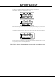
BATTERY BACK UP Your XK-3C uses a battery-backed RAM to remember your changes to the Parameters. When the battery voltage becomes low, the Display will show: If you see these messages, you should immediately back up your parameter changes, if you have made any.
Table Of Contents IMPORTANT SAFETY INSTRUCTIONS ............................................ 2 IMPORTANT - PLEASE READ .......................................................... 4 BATTERY BACK UP ......................................................................... 5 SETTING UP ............................................. 29 Index ................................................................................... 8 DRAWBARS™ ...........................................................................
SETTING THE PARAMETERS ................. 55 DRAWBAR .................................................................................... 56 Setting the Manual Part (LOWER and UPPER) ............................................. 56 Setting the PEDAL Part ................................................................................ 57 MIDI ............................................................................................. 96 MIDI TEMPLATE .........................................................
Index A Adjust Preset 24, 82, 100 Assign 60 C Master Tune 67 Menu Mode 50 MIDI 86, 96 Modulation 63 Noise Gate 83 O D Overdrive 25, 39, 78 Default 82 Demonstration 21 Display 65 Drawbar 24, 32, 56, 62 P E Effect Loop 16 Envelope 56 Equalizer 80 Expression 23, 64 F Fold-Back 56 Foot Switch 23, 64 Footage 32 Function Mode 51 I Initial Status 20 Internal Zone 92 Part 26 Pedal Keyboard 89 Percussion 24, 37, 71 Pitch Bend 23, 62 Play Mode 49 Preset 58 Preset Key 24 R Registration 24, 32, 36 Reverb 2
MAIN FEATURES 9 ACCURATELY REPRODUCES THE TONE-WHEEL SOUND. Your new XK-3C contains (96) independent oscillating digital tone-wheels that accurately reproduce the sound of the Vintage B-3/C-3. In addition, this keyboard has full polyphony. KEYBOARD OPERATES LIKE THE VINTAGE MODELS. This keyboard operates exactly like the vintage B-3, C-3, etc did. Presets are selected by means of the Reverse Colored Keys. Vibrato effects can be selected by the rotary Vibrato control.
NAMES AND FUNCTIONS 10 Front Panel 1 3 10 5 9 17 18 12 11 2 4 6 7 8 19 14 15 16 13 11. PARAM Button Selects Parameters. UPPER LEFT 1. MASTER VOLUME Knob Controls the total volume. 2. CONTROL Button Sets up various controls. 3. TONE Knob Controls the tone quality. 4. TONE TYPE Button Assigns the function of TONE CONTROL (3). 5. TUBE OVERDRIVE Knob Controls the distortion of TUBE AMP (6). 15. MENU/EXIT Button Recall the MENU screen.
20 22 23 24 21 33 29 30 252627 28 DRAWBARS 31 32 34 UPPER RIGHT 20. LEFT DRAWBARS Controls UPPER part or B key harmonics. 29. REVERB Button Switches on and off the REVERB Effect. 21. LEFT DRAWBARS LED Indicates the function of the left drawbars. 30. USER Button With this button you can assign the function you want. PEDAL SUSTAIN ON/OFF is assigned as the factory setting. 22. PEDAL DRAWBARS Controls PEDAL part harmonics. 23. RIGHT DRAWBARS Controls LOWER part or A< key harmonics. 24.
End Block 35 36 40 41 37 38 39 WHEEL KEYBOARD 35. PITCH BEND Wheel Slides the pitch up or down. The pitch goes up when moved up, and goes down when moved down. 36. MODULATION Wheel On this keyboard, this is used mainly to send MIDI information to connected MIDI equipment. LESLIE 37. LESLIE BRAKE Button This button selects whether to produce sound from the stopped rotor (=Brake) or not to use the Leslie effect (= Through) when the LESLIE ON(38) Button is “off”. Brake is ON when the LED is on.
Rear Panel 42 43 44 45 46 47 48 49 LEFT SIDE OF REAR 42. AC Inlet Connects the A.C. Power Cable. CAUTION This keyboard shall be connected to a MAINS socket outlet with a protective earth connection. 43. POWER Switch This switch turns the power ON and OFF. CAUTION Even when the POWER switch is turned off, electricity is still flowing to the instrument at the minimum level. When you are not using the instrument for a long time, make sure you unplug the power cord from the wall AC outlet.
51 52 54 53 55 EFFECT LOOP 56 SOUND OUTPUT TERMINAL 51. SEND This jack is for sending to external Effects. The signal after passing through the built-in Tube Amp. is sent out. If you insert a plug into this jack, it disconnects the internal unit, and signals are not put out from the output jack, except the signal input from RETURN jack. (The rated output level is 1.23V +4dBm. The output impedance is 600Ω.) 52. RETURN/EXT IN This jack is for receiving external Effects.
HOOK-UP *# 1 :- % Owner’s Manual
BASIC HOOK-UP 16 See the figure below for connection. Amplifiers or speakers are not mounted in this keyboard. You must connect an external amplifiers and speakers (or Powerd Speaker) in order to hear the keyboard sounds. You can also enjoy playing this keyboard by connecting Stereo Headphones to the Headphone Jack. Be sure to do the connection after you switch the Power OFF on this keyboard and all connected equipment.
CONNECTING THE LESLIE SPEAKER 17 This keyboard is equipped with a 11 Pin Leslie Connector, so you can directly connect the Leslie Speaker. Do this connection after switching OFF the keyboard. Connect the Leslie Speaker to the 11 Pin Terminal on the keyboard, with the exclusive 11-Pin Leslie Cable (= LC11-7M - to be separately purchased - with the other Leslie Speaker accessories). Adjust the setting of the “EXT. LESLIE CH”, in accordance with the Leslie Speaker connected. (P. 74) eg.
CONNECTING THE MIDI KEYBOARD 18 You can upgrade this keyboard to an organ by connecting an external MIDI Keyboard and pedal keyboard. MIDI Keyboard Expression Pedal EXP-100F MIDI Pedal Keyboard 1. Hook-up external MIDI keyboard and pedal keyboard per the figure above. 2. Use the MIDI Template “Seq. Record” of this keyboard. (P. 96 #1) 3. To use Expression Pedal, set the parameter “EXPRESSION SOURCE” for the model of expression pedal that you have connected. (P.
TURN ON AND PLAY *# 1 :- % Owner’s Manual
POWER ON 20 HOW TO POWER ON After connecting your XK-3C to the power outlet, please perform the following steps before switching on the power. To avoid possible damages to speakers, please do not change the order of the steps. STEPS TO TAKE 1. Set the MASTER VOLUME Knob at 0 (minimum), before switching the power on. 2. Switch on the POWER on the rear panel. “PLAY” Mode appears, following the TITLE, in the Display window.
LISTEN TO THE DEMONSTRATION PERFORMANCE 21 In your XK-3C, the demonstration performance is built in for introducing the features and sound. STEPS 1 Touch and hold the [MANUAL BASS] and [SPLIT] Button for 2 seconds. The Display will be as shown in step 2. NOTE: You can locate this mode another way. Touch the [MENU/EXIT] Button to display the MENU, touch the [PAGE] Button and select page E, and touch the [3]DEMO. 2 Press the [PAGE] Button and select a desired song.
PLAY WITH THE COMBINATION PRESET 22 You can record various settings to the Preset Keys mounted on the left-hand side of the XK-3C. This is called “Combination Preset”. The Combination Preset consists of the “BANK” and “KEY” (2-dimensional) such as “C-D”, and appears for each setting on the Display. Combination Presets C C< D D< E Key F F< G G< A A< B Adjust B Bank C C< D D< E F F< G G< A A< B The Preset data is recorded in the Banks C to B at the factory. Thus you can start playing immediately.
PLAY WITH THE CONTROLLERS 23 Your performance will be more expressive, if you play on the manual using the controllers. You will see on this page how to use the controllers generally used with the electronic musical instruments. (How to use the exclusive Hammond Organ controllers is shown on the next page.) PITCH BEND WHEEL This is used to slide the pitch up or down while playing. The frequency goes up when you move it back, and it goes down when you move it forward.
TRY TO MAKE YOUR OWN SOUND 24 You will be able to freely produce your own sound by using the exclusive features of your HAMMOND ORGAN, such as Drawbars and Percussion sound, as well as Vibrato and the Leslie effects. The steps to take after you receive your XK-3C from your dealer are as follows: SELECT THE PRESET KEY [B] First select the Preset Key [B]. This is a special key, also called “Adjust Preset”.
ADD EFFECTS VIBRATO & CHORUS “Vibrato and Chorus” slightly changes the Drawbar pitch at a certain ratio and add warmth to the sound. [UPPER] Button Switches on and off the Vibrato effect. The LED turns on when it is ON. [VIBRATO & CHORUS MODE] Knob Controls the Vibrato Depth and switches to and from the Chorus effect. The degree of the depth corresponds with the number.
Divide the keyboard into two parts - left and right. [SPLIT] This keyboard has only a single manual. But you can change the setting and play it as it was a double keyboard organ, using this “SPLIT” function. [SPLIT] Button Switch on the LED by pressing the button, to “split” the manual. The factory “SPLIT” setting is to divide it between B and C in the center. NOTE: Split Point or Octave can be moved. (P. 92 #4) NOTE: The Split function does not work, when the MIDI IN jack is used for “LOWER/PEDAL”.
STORING REGISTRATIONS IN COMBINATION PRESET All the afore-mentioned settings can be memorized to the Combination Preset. The data stored at the factory can also be freely re-written. EX. Memorize to “F - D”. 1 Light 1. While pressing the [BANK] Button, press the Preset Key [F]. The LED on the Preset Key indicates BANK while the [BANK] Button is pressed. Press and Hold NOTE: The LED goes out if you release the button. This means the Preset is not final. Touch 2 Flash to On 2.
*# 1 :- % Owner’s Manual
SETTING UP *# 1 :- % Owner’s Manual
SOUND ENGINE STRUCTURE 30 SYSTEM STRUCTURE OF THIS KEYBOARD *# 1 :- % Owner’s Manual
To fully enjoy playing this keyboard, please read the following section of this manual. See the illustrated System Structure of your keyboard on the left page. TONE-WHEELS The sound source or “engine” of Hammond Organ is the Tone-wheels. They are like the strings and pick-ups on the electric guitar. While running, each of the 96 Tone-wheels keeps oscillating at a different pitch/frequency. KEYS Each of the sound signals made by the 96 Tone-wheels is switched at each key.
DRAWBARS™ 32 The 9 Drawbars (plus 2 for the Pedal) on this keyboard are used to make the basic sounds. Each Drawbar is marked with the numbers 1 - 8. If you push back the Drawbar until you can not see any number at all, the sound of the Drawbar is not heard. If you pull it out to the fullest position THE SOUND LEVEL is maximum. Except when the Preset Key is B, the actual Drawbar Registration is the value displayed in the (display-)window.
MANUAL DRAWBARS WHITE DRAWBARS In each Drawbar set, the white Drawbar (8') on the left end makes the basic/ fundamental sound. The other white Drawbars get higher by the octave to the right. BLACK DRAWBARS The sounds of the black Drawbars, too, play important roles in building rich tones. Their pitches are fifth and third to the fundamental. They contain the elements of all different harmonics of such as the sweet and soft horn, mellow strings and so on.
DRAWBAR REGISTRATION PATTERNS The Drawbar Registration is matched by digits, if precisely. However, in the usual play, it is rather reasonable to remember the typical combinations of the 9 Drawbars by their forms/shapes.
Diapason family (check mark pattern) Accomp.
3 SETS OF DRAWBARS AND PARTS On this keyboard, there are 3 Parts: UPPER, LOWER and PEDAL, and each of them has the corresponding Drawbars. The manual on the keyboard is usually assigned to the UPPER position. If you want to play the LOWER or PEDAL Part, use the Split or Manual Bass functions, or connect the MIDI keyboard and assign each part. There are lamps(= LED’s) in front of the two sets of 9 Drawbars, marked with “UPPER/ B” and “LOWER/A<”. They indicate the assignment of the Drawbar Sets.
PERCUSSION 37 The attack feeling of the percussion is a Hammond exclusive. Percussion is usually used with the Drawbar sound. [SECOND] BUTTON The second harmonic, or 4' Drawbar decay, is added to the UPPER Part. To use this, press the [SECOND] button, and the LED will light. [THIRD] BUTTON The third harmonic, or 22/3' Drawbar decay, is added to the UPPER Part. By mixing it with the Drawbars, power and solidness is obtained. To use this, press the [THIRD] button, and the LED will light.
VIBRATO & CHORUS 38 VIBRATO adds warmth to the tone, by slightly changing the Drawbar pitch at a certain speed. You can also add richness to the sound by mixing the Vibrato sound with the fundamental (= Chorus Effect). [UPPER] BUTTON This switches ON and OFF Vibrato and Chorus Effects. It affects the UPPER Part. To get this effect, press the button and the LED will light. [LOWER] BUTTON This switches ON and OFF Vibrato and Chorus Effects. It affects the LOWER Part.
TUBE AMP 39 The TUBE (= Vacuum Tube) AMP produces a unique “Tube Feeling” sound. By changing the amount of the Drive, various Tube Sound is obtained, from the unclipped clean to the hard-distorted fuzzy, raspy Overdrive sound. [TUBE AMP] BUTTON This is for determining whether or not to go through the Tube Amp circuit. To get this effect, touch the button and and the LED will light. NOTE: You can see the tube through the ventilation hole on the back.
LESLIE 40 LESLIE EFFECT is the simulated sound of the rotating speakers. If you connect the real Leslie speakers to this keyboard, it controls those (speakers). [ON] BUTTON If you touch this button, the LED will light, and the rotor starts turning. Also the voice is heard thru the rotary channel. [FAST] BUTTON BUTTONS AND LESLIE MODES This switches the speed of the rotor in two steps. It switches every time you touch it. When the LED is ON, it is FAST, and when the LED is off, it is SLOW.
EQUALIZER & REVERB 41 The Equalizer and the Reverb effects give the final touch to the tone. The Equalizer regulates the tone, and the Reverb adds the resonance of the hall performance. You can control portions of their functions on the panel buttons and knobs EQUALIZER [TONE] KNOB One optional Parameter out of the Equalizer is assigned and regulated. TONE is assigned as the factory setting. If you turn this knob to the right, it gives flat characteristics and, if to the left, the treble is decreased.
COMBINATION PRESETS 42 The settings you have made can be recorded into the Combination Presets. BANK AND KEY Combination Presets C C< D D< E F Key F< G G< A A< B Adjust B Bank C C< D D< E F F< G G< A A< B The combination preset chart to the left, shows the [BANK] and the [KEY], information. Access is made by the Preset Keys. To select the [BANK], press the key, holding down the [BANK] button. To select the [KEY], just press the Preset Key.
NAME THE COMBINATION PRESETS 1 Go to the MENU. Touch the [MENU/EXIT] button. The MENU mode will be displayed. 2 Go to PAGE A. If the PAGE A is not displayed, touch the [PAGE] button and go to PAGE A. 3 Go to the PRESET FUNCTION mode. Touch the [2] PRESET button and go to the PRESET FUNCTION mode. 4 Input THE NAME. You can store names up to 10 letters. [PARAM] BUTTON: [VALUE] BUTTON: moves the cursor. selects letters.
RECORD INTO THE COMBINATION PRESETS EXAMPLE: 1 Record into “F-D”. Select the Bank. While holding down the [BANK] button, touch the Preset Key [F]. The LED on the Preset Key indicates the BANK while you are holding down the [BANK] button. Light Press and hold NOTE: The LED will be OFF, if you release the button. This means the Preset is not stored. This operation is not necessary, if you do not change the Bank. Touch 2 Select the Key.
LOCKING THE COMBINATION PRESET You can lock the Combination Preset to avoid calling it out by mistake while playing. To lock the Combination Preset, press both the [BANK] and the [REC/JUMP] buttons for longer than 1 second, after calling out the Ccombination Preset you want to lock. “Preset LOCKED” will be displayed for a certain length of time and the Combination Preset will be locked.
*# 1 :- % Owner’s Manual
USING THE CONTROL PANEL *# 1 :- % Owner’s Manual
OPERATION CONTROL PANEL 48 You now know you can do many settings by using the buttons and knobs on your keyboard. You can do even finer settings like the delicate speed of the Leslie Effect or the MIDI equipments, using the display buttons on the Control Panel. There are PLAY, MENU and FUNCTION modes in the display. The buttons and knobs in each mode is explained on the following pages.
PLAY MODE 49 The PLAY MODE is the basic display for all the operations. The necessary informations for the normal play will be displayed. There are two types of PLAY MODE screens to display the Drawbar Registration. One is by showing the length of the bars and the other by digits. To locate this mode: 1. Immediately after powered ON and the start up process is complete, the PLAY mode is displayed. If a different mode is displayed, touch the [PLAY] button. 2.
MENU MODE 50 The MENU mode is the path for each function. To locate this mode: Touch the [MENU/EXIT] button. There are several pages which contains many various FUNCTION displays. Move from page to page and find the item where you want to go and touch the numbered button to see the desired display. FUNCTION ITEM (If none, blank.) HOW TO READ THE DISPLAY PAGE BUTTON OPERATION IN THIS MENU Moves from a page to another.
FUNCTION MODE 51 The FUNCTION MODE is for making each setting and adjustment. There are many displays, but the basic operation is the same. HOW TO READ THE DISPLAY This shows there are PAGEs above (or below). PARAMETER This shows there is a PAGE on the right (or on the left). CURSOR PAGE NAME VALUE CURSOR (Flashing VALUE) In the display window of this keyboard, the CURSOR is displayed in the flashing style, while the most popular indicator - cursor used on the PC, the mobo, etc.
Example of operation: Adjusting the DECAY TIME of the Percussion [FAST] 1 Go to the MENU Mode. Touch the [MENU/EXIT] button. The [MENU] mode is displayed. 2 Select the PAGE. Search for the PERCUS page, using the [PAGE] button. “PERCUS” is on PAGE B. So select PAGE [B]. 3 Touch the Number button. Touch the [2] button for “PERCUSS”. Now you are on the (first page) of the Percussion Function display.
4 Move the CURSOR to the Parameter you want to change. DECAY TIME is on the “DECAY” PAGE. Move to that page using the [PAGE] button. “FAST” is on the right end. Move the CURSOR (flashing value) to underneath “FAST” using the [PARAM] button. 5 Change the value. Decrease the value, using the [VALUE] button or the [VALUE] knob on the right bottom. NOTE: 6 Repeat the operation 1 - 5, if you want to change the other parameter, too. Record into the Combination Presets.
SHORT CUT TO THE FUNCTION MODE 54 Each button on the panel has a “SHORT-CUT” capability, so that you can easily go to each Function mode. By holding down the button, you can easily go to the desired mode display. You can save time to search the page for the parmeters you want to change. Example of operation: Move to the Percussion Function Mode.
SETTING THE PARAMETERS *# 1 :- % Owner’s Manual
DRAWBAR 56 In this mode, you can set the Parameter relating to the Drawbar sound of each part. To locate this mode: Touch the [MENU/EXIT] button and display MENU, touch the [PAGE] button and select PAGE A and choose [1] DRAWBAR. 7 11 8 9 2 3 12 10 5 13 6 4 1 Setting the Manual Part (LOWER and UPPER) TONE-WHEEL SET 1. TONE-WHEELS Select the TONE-WHEEL SET (waveform) for the manual part.
Setting the PEDAL Part 7. TONE-WHEELS This allows you to select the Tone-wheel set (waveform) of the PEDAL Part. Normal Normal:The traditional B-3/C-3 Tone-wheel sound Muted: Analog-oscillating sound represented by the X-5. Muted Synth1: Sawtooth waveform with sweep filter. Synth1 Synth2: Dull square waveform. Synth2 NOTE: You can locate this page by holding down the [MANUAL BASS] Button as well. 8. ATTACK This allows you to set the Attack Rate and the Key-Click Volume at ATTACK and RELEASE.
PRESET 58 In this mode, you can name your Combination Presets and determine how to recall them. To locate this mode: Touch the [MENU/EXIT] button and display MENU, then touch the [PAGE] button to select PAGE A and touch the [2] PRESET button. 3 3 2 4 5 6 7 1 8 9 6. PRESET LOAD - INTERNAL ZONE (B) PRESET NAME This allows you to determine whether or not to recall the Parameters relating to the Internal Zone such as SPLIT or MANUAL BASS. 1.
EFFECTIVE USE OF LINK-LOWER/PEDAL This is the function to switch/record only from the connected MIDI equipment, and not to operate the Preset for LOWER and PEDAL Part on this keyboard. The Preset Keys on B-3/C-3 are independent, key by key, and so they were operated independently. This function simulates that. WHEN LINK LOWER/PEDAL IS ON: When you recall the Combination Preset by the Preset Key, the content of all UPPER/LOWER and PEDAL Parts will change.
ASSIGN 60 In this mode, the settings of the ASSIGNABLE CONTROLLERS are made. The purpose is assigning functions whenever necessary for controlling the external MIDI equipment using the external zones or controlling vibrato or Leslie on the organ by your right hand. For making the settings easily, several assigning patterns are available - prepared as templates. 8 To locate this mode: Touch the [MENU/EXIT] button and display the Menu. Select Page A by the [PAGE] button, and touch the [3] ASSIGN button.
8 9 10 11 12 13 2 3 4 5 6 7 11 5 12 13 6 7 ASSIGNABLE BUTTONS The following functions are assignable to the ASSIGNABLE BUTTONS. EXT CH EXT.. SWIT SWITCH This function switches SEND ON/OFF to the external zone. AST BRAKE,, ON, F FAST LESLIE BRAKE These function are what the LESLIE [BRAKE], [ON]. [FAST] buttons do. VIB. L OWER, UPPER LOWER, These functions are what the VIBRATO [LOWER], [UPPER] buttons do. STOP,, CONTINUE CONTINUE,, ST START STOP ART These functions send each MIDI message.
CONTROL 62 To locate this mode: In this mode, you can control the setting relating to each controller. You may change the roles of several knobs and switches mounted on this keyboard. Also, on the rear panel are two jacks for connecting the Foot-switch and the Expression Pedal. You must choose either of them in this mode. 22 1. Touch the [MENU/EXIT] button and display the MENU and select PAGE A by the [PAGE] button, and then touch the [4] CONTROL button. 2.
MOTOR There is no pitch-bend function on the B-3/C-3. So some musicians turned off the power while playing in order to get that effect. If the B-3/C-3 is turned off, the Tone-wheel motor gradually slows down and stops, and the amplifier does as well. This function is to simulate that on this model. 20 HOW PITCH BEND MODE WORKS 6. BEND - MODE (P) It switches the function of the PITCH BEND wheel. BEND BEND: You can slide the pitch by rotating the PITCH BEND wheel.
EXPRESSION 10. EXPRESSION - SOURCE (G) Determines what to use for controlling the Expression. PED1(NORM) PED1(NORM): Uses V-20R etc. PED1(REV): PED1(REV) Uses KORG XVP-10 etc. EXP -100 EXP-100 -100: Uses EXP-100F. IN: MIDI IN Uses the Expression Information received at the keyboard channel UPPER. 11. EXPRESSION - MONITOR Displays the present Expression Value.
18. FOOT-SWITCH - 1 TIP (G) This is for setting the function of the Foot Switch 1 jack. If you are using the Foot Switch with a stereo plug, this sets the function on the tip contact. OFF OFF: Does not work. ALT MOM: LESLIE S/F AL T, MOM These are for switching SLOW/FAST of the Leslie Effect. At ALT, SLOW/FAST is alternately switched at each step of the Foot Switch, and it switches OFF if pressed for longer than 1 second.
THE EFFECTIVE USE OF THE CONTROL MODE The DRAWBAR - CONTROL MODE is normally set on the “UPPER/LOWER” side. “UPPER A
TUNE 67 In this mode, you can tune and transpose for playing in ensemble with the other instruments. To locate this mode: Touch the [MENU/EXIT] button (MENU will displayed), select PAGE B by the [PAGE] button and touch the [3] TUNE button. 1 2 1. TRANSPOSE You can transpose the entire keyboard by the semi-tone. The setting range is -6 to +6.
CUSTOM TONEWHEELS 68 In this mode, you can regulate each Tone-Wheel Set of the Manual Keyboard, wheel by wheel. The Tonewheel Set consists of 96 Tonewheels of different pitches, and one wheel corresponds with plural notes and the feet of the Drawbars. The relation is complicated. For example, the middle C of the 8' and the C one octave lower of the 4' use the identical wheel. In this keyboard, you can save 5 types of settings per 1 Tone-Wheel Set. We call this “CUSTOM TONE- 4 5 6 7 WHEELS”.
4. WHEEL NUMBER Select the Number of the Wheel you want to regulate. To select the Wheel Number, select the [VALUE] button or the [VALUE] knob here, or slightly move the feet of the Drawbar while depressing the key you want to regulate. (See the illustration on the right.) When the Wheel Number is selected, each parameter for the wheel (5, 6, 7, 8) is displayed. 5. LEVEL This is for setting the volume of this wheel. The setting range is -20 to +2dB. If you increase the value, it gets louder.
RECORD THE CUSTOM TONEWHEELS The Tonewheel Parameters (= 3 - 8 of the previous Section) are for determining the Custom Number for recording. The Custom Number is selected and used, when you play. 1 Enter the Custom Name if necessary. 2 Touch the [REC/JUMP] button in the setting mode of the Tonewheel Parameters. The mode for selecting the Custom Number to be recorded will be displayed. 3 Select the Custom Number to be recorded by the [PAGE] button.
PERCUSS (PERCUSSion) 71 In this mode, you can set the parameter of the PERCUSSION sound. To locate this mode: 1. Touch the [MENU/EXIT] button and display MENU, then select PAGE B by the [PAGE] button and touch [4] PERCUSS button. 2. Or, hold down either [SECOND],[THIRD],[FAST],or [SOFT] button for a certain length of time. 8 9 5 6 3 4 1 1. LEVEL - SOFT 2. LEVEL - NORMAL These are for setting the Volume of Percussion.
LESLIE 72 In this mode, you can do the setting for the built-in Leslie Effect and the External Leslie Speaker. There are many parameters for the built-in Leslie Effect, and so you can do various settings, but not per each Combination Preset independently. The parameters are treated by the group called “CABINET”. You can select the CABINET NUMBER in the Combina- tion Presets. To locate this mode: 1. Touch the [MENU/EXIT] button to display the MENU.
4. SPEAKER This sets the type of the imaginary speaker. RotSmall RotSmall: A small Leslie speaker represented by Leslie 145 RotLarge: A large Leslie speaker represented by Leslie 122 RotLarge Station: A stationary speaker represented by Hammond PR-40 Station 5. SLOW SPEED - HORN 12. SLOW SPEED - BASS Here the Speed of the Rotor is set for Slow mode. The setting range is 0, 24 - 318 rpm. It does not rotate at 0. 6. FAST SPEED - HORN 13. FAST SPEED - BASS Here the Speed of the Rotor is set for Fast mode.
18. MIC - ANGLE This is the parameter to set the LOCATIONS of the two Microphones for the imaginary Leslie Speaker. The ANGLE decides the distance between the two mikes. The setting range is 0 - 180 degrees. The farther, the more stereophonic feeling it gives. 19. MIC - DISTANCE This is the parameter to set the DISTANCE between the imaginary Leslie Speaker and the Microphones. The setting range is 0.3 - 2.7m. The more the value increases, the less effective it gets.
RECORD THE CABINETS The Leslie parameters (2 - 19 of the previous paragraph) can be recorded with the Cabinet Numbers, and you can choose and use them in each Combination Preset. 1 Enter the name for the Cabinet as you want. 2 Touch the [REC/JUMP] button in the setting mode of the Leslie Parameter. The Cabinet Selection mode is displayed. 3 4 Select the Cabinet Number to record by the [PAGE] button. Touch [4] OK, and it is recorded. The display during the recording treatment shows as illustrated.
VIB&CHO (VIBrato and CHOrus) 76 In this mode, you can change the settings relating to each Effect for Vibrato and Chorus. To locate this mode: 1. Touch the [MENU/EXIT] button to display the MENU, select PAGE B by the [PAGE] button, and then touch the [4] VIB&CHO button. 2. Or, hold down the Vibrato & Chorus [UPPER] or [LOWER] button for a while. 4 5 1 6 2 7 8 9 3 1. VIBRATO - RATE This is for setting the Speed of the Vibrato and Chorus Effect. The setting range is 6.10 - 7.25 Hz. 2.
VIBRATO AND CHORUS OF HAMMOND ORGANS On string instruments, the vibrato effect is created by changing the string tension by ones fingers. On wind instruments, by changing the strength of breath. On electronic instruments with analog circuitry, by modulating the oscillator. As the rotation of the tone-wheels of the B-3/C-3 is stablized by the synchronous motor, you can not obtain the oscillation accompanied by a vibrato effect.
OVERDRIV (OVERDRIVe) 78 In this mode, you can change the settings relating to each Effect for Overdrive and Vibrato/Chorus. To locate this mode: 1. Touch the [MENU/EXIT] button to display the MENU, select PAGE C by the [PAGE] button, and then touch the [1] OD/VIB button. 2. Or, hold down the [TUBE AMP] button for a while. 5 6 7 1 4 2 1. PREAMP - TYPE 6. BLEND This is for choosing the Tube Amp Circuit.
B I A S V O LTA G E A N D N O N L I N E A R DISTORTION To make the vacuum tube function as a audio amplifier, a minus voltage called bias voltage is added to the input terminal (called grid) as well as the audio signal. Although, the bias voltage is generally fixed so that the distortion of the output wave-form of the tube is at the minimum, the bias voltage can be changed when the tube amplifier is overdriven on this model.
EQUALIZ (EQUALIZer) 80 In this mode, you can adjust the settings for the Equalizer. An Equalizer is used to adjust the tonal quality. The built-in Equalizer consists of 3 bands and Tone Control. With the 3 bands ranging bass to treble, you can boost or cut any of them. To locate this mode: 1. Touch the [MENU/EXIT] button for the MENU, select PAGE C by the [PAGE] button, and then touch the [2] EQUALIZ button. 2. Or, hold down the [TONE TYPE] button for a while. 6 1 2 3 4 5 1.
REVERB 81 In this mode, you can change the setting for the REVERB EFFECT. To locate this mode: 1. Touch the [MENU/EXIT] button for the MENU display, select PAGE C by the [PAGE] button, and then touch the [4] REVERB button. 2. Or, hold down the [REVERB] button for a while. 6 3 3 4 1 1. DEPTH 2 5. DELAY FEEDBACK This sets the Depth (= Volume) of the Reverb Effect. The setting range is 0 - 15.
DEFAULT 82 In this mode, you can go back entirely or partially to the default setting as per shipped from the factory. To locate this mode: Touch the [MENU/EXIT] button for the MENU display, select PAGE E by the [PAGE] button, and then touch the [1] DEFAULT button. 1 2 3 4 5 6 To initialize each parameter, touch the [PARAM] button and then [4] OK. 1. ADJUST PRESET Initializes the content of the Preset Key [B].
SYSTEM 83 In this mode, you can set the SYSTEM PARAMETERS of this keyboard and the display information. To locate this mode: Touch the [MENU/EXIT] button to display the MENU, select PAGE E by the [PAGE] button, and then touch the [2] SYSTEM button. 3 6 7 4 5 2 1 1. NOISE GATE - RETURN Switches the action of the Noise-Gate of the Effect Loop and the Return jack. THRESHOLD 1 1: 2: THRESHOLD 2 The audio output is switched ON/OFF according to the volume input to the Return jack.
*# 1 :- % Owner’s Manual
MIDI *# 1 :- % Owner’s Manual
MIDI 86 What is “MIDI”? MIDI stands for Musical Instrument Digital Interface. (The capital letters of these four words.) MIDI is for exchanging the performance information between an electronic musical instrument and a sequencer etc. MIDI is an international standard, by which instruments made by different manufacturers can be connected to communicate with each other. The control information is exchanged, such as the performance infos.
MIDI CHANNEL MIDI has the “MIDI CHANNELS” 1 - 16. Thus, you can send your playing information divided into 16 channels through one MIDI cable. However, the channel must match between the sender and the receiver. Otherwise, you can not “hear” what the other “says”. MAJOR MIDI MESSAGE The MIDI infomation is grouped into the channel message per each of the 16 channels and the system message for the total channels. The main MIDI message is as follows: See for details in the MIDI IMPLEMENTATION CHART.
MIDI STRUCTURE 88 This organ has only a single keyboard. However, its sound engine provides 3 parts of UPPER/LOWER/PEDAL, and, furthermore, 3 “EXTERNAL ZONES” for the internal keyboard of this organ and 3 for external keyboard, for controlling external MIDI equipment. For these special reasons, this unit has 9 MIDI channels.
EXPANDING THE KEYBOARD 89 This is the method how to connect the XK-3C to the MIDI keyboard and play on the full manual (3 keyboard) instrument. MIDI Keyboard Expression Pedal EXP-100F MIDI Pedal Keyboard 1. Hook up as shown above. 2. Recall “Seq. Record” by the MIDI template. 3. If you use the Expression Pedal, set the “Expression Source” corresponding to the connected Expression Pedal. (P.
RECORDING AND PLAYING THE PERFORMANCE 90 This is the method to record and playback your performance, by connecting the Sequencer or Computer to your XK-3C. Recording to the Sequencer or the Computer MIDI Keyboard 1. Hook up as illustrated. Connect the MIDI OUT to the MIDI IN of the Sequenser. 2. Recall “Seq. Record” by the MIDI template. By this, the performance on this module is sent to the MIDI channel 1, 2 and 3. 3. 4. 5. 6. Set the Keyboard Channel that you want. Start the Sequencer recording.
CONTROLLING THE EXTERNAL MIDI EQUIPMENTS 91 You can control the External MIDI Equipment such as Sound Modules up to 3 (internal keyboard), 2 (external Lower keyboard), 1 (external Pedalboard) Zones by your XK-3C. MIDI Keyboard MIDI Pedal Keyboard MIDI Sound Module 1. Hook up as shown above. Connect the MIDI OUT of this unit to the MIDI IN of the equipment you want to control.
ZONES 92 To control the external MIDI equipment, a certain range of the manual keyboard of this keyboard is used for that. Each of them is called the “EXTERNAL ZONE”. At the same time, you can set the oscillating range (= “INTERNAL ZONE”) of the built-in sound engine and play it on the same single keyboard. Also, each MIDI keyboard connected to the MIDI IN (LOWER and PEDAL) can control the MIDI equipment 9 10 1 2 11 12 3 13 by the EXTERNAL ZONE.
20 23 21 24 22 EXTERNAL ZONE 3 EXTERNAL ZONES (XU1, 2, 3) are provided for the internal keyboard of this organ, 2 (XL1, 2) for the MIDI keyboard connected to the MIDI IN (LOWER) (hereinafter Lower Keyboard) and 1 (XP1) for the MIDI keyboard connected to the MIDI IN (PEDAL) (hereinafter Pedal Keyboard). You must switch the MIDI IN mode to “LOWER/PEDAL”, when you use the External Zones on the Lower Keyboard and the Pedal Keyboard (P. 96 #2). 9.
9 10 1 2 11 12 13 3 4 18. NOTE - PAN This is for setting the Pan (= Control Change #10) of this Zone. 19. NOTE - VELOCITY This is for setting the Velocity Curve to send to this zone. The setting range is OF, 1 - 4. The velocity of OF is fixed at 100. At 1 - 4, the more the value increases, the intense velocity is sent regardless how light the key is touched. 20. EXPRESSION - MINIMUM 21. EXPRESSION - MAXIMUM This is for setting the range of the expression to “compress” to send to this Zone.
20 23 21 24 25 22 MIDI
MIDI 96 This is the mode to do the basic setting of the MIDI. To locate this mode: Touch the [MENU] button to display the MENU, select PAGE D by the [PAGE] button, and then touch the [2] MIDI button. 13 14 15 2 3 4 5 6 7 8 1 4. MIDI TEMPLATE 1. This is for switching ON/OFF the transmission of (= send and return) NRPN (Non-Registered Parameter Number). On this keyboard, it switches ON/OFF whether to send/receive the message of Drawbar Fold-Back, Leslie ON, etc.
9 9. 10 11 12 DEVICE ID This sets the Device ID for sending/receiving the system exclusive messages such as Memory Dump. DETAILS OF THE MIDI TEMPLATES The setting range is 1 - 32. For the details at each Template's call out, refer to 10. RECEIVE DUMP This is for determining whether or not to receive the MEMORY DUMP.
*# 1 :- % Owner’s Manual
SAVE THE SETUP *# 1 :- % Owner’s Manual
SAVE THE SETUP 100 On this keyboard you can save the setting of each Parameter as a file, into the CompactFlash™ card (hereinafter “CF card”). Eject Button CF CARD YOU CAN USE The manufacturer recommends HCF-32 as your CF card. Please consult URL: http://www.hammondsuzuki.com before you try to use other cards on the market. CF CARD SLOT 1. 2. 3. First please read the label on the CF CARD carefully and insert it correctly. To take out the card, push the EJECT button on the right hand side of the slot.
INITIALIZE THE CF CARD 101 The CF CARD must be “INITIALIZED” first (= before you use it). Perform the following, step by step, to do the initializing operation. This operation erases all data in the CF card. 1 4 Touch [4] CF FORM. The FORMAT mode is displayed. Insert the CF card into the slot. 2 5 Touch the [4] OK button. The Confirmation message is displayed. Touch the [MENU/EXIT] button. 6 3 Touch the [4] YES button. The initialization starts. It takes only a few seconds.
OPERATE THE SETUP 102 Save or Load the SET UP to/from the CF card in the SETUP mode. In this mode, you can do all the operations except the initialization of the CF card. To come to this menu: Touch the [MENU] button to display the MENU, select PAGE D by the [3] SETUP button. HOW TO READ THE DISPLAY Setup Name This indicates there is another SETUP file above (or below). Rename Load Save Delete SAVE THE SETUP 1 4 Check that the CF CARD is correctly inserted. 2 Go to the SETUP mode.
CHANGE THE SETUP NAME 1 4 Select the SETUP file you want to change the name. 2 Move the cursor to the right end by the [PARAM] button. [ENT] will be displayed. 5 Touch the [3] NAM button. You have come to SETUP NAME INPUT mode. 3 Input the new SET UP NAME. Touch the [4] ENT button. The SETUP NAME will be changed. [PARAM] BUTTON Move the cursor. You can use up to 16 letters. [VALUE] BUTTON Choose the letters by this. You can use Large and small Alphabets, digits and signs/ symbols.
LOADING THE SETUP HOW TO DELETE THE SETUP After the operation, the settings already in this keyboard will be replaced by the newly loaded SET UP. So you had better save them in advance. 1 1 Check the CF card is correctly inserted. 2 Check the CF card is correctly inserted. Come to the SETUP mode. 2 3 Come to the SETUP mode. 3 Choose the SETUP file you want to delete by the [PAGE] button. 4 Choose the SETUP file to load by the [PARAM] button. Touch the [4] DEL button.
TROUBLE SHOOTING *# 1 :- % Owner’s Manual
TROUBLE SHOOTING 106 Malfunction of the buttons, the keys, etc. Turn off the POWER switch once, then turn it on again. If this procedure is not successful, turn off the POWER switch. While pressing [REC/JUMP] button, turn the POWER switch on again. (Note that in this case, all parameters return to their factory-preset status.) No sound is produced when the keys are pressed. The MASTER VOLUME is at the minimum setting. Adjust the volume with the MASTER VOLUME control. (P.
APPENDIX
Appendix Custom Tone-wheel Templates BType1, BType2 Real B-3 This template faithfully simulates the classic model, B-3. It contains low motor hum and some leakage noise. 80’s Clean This template simulates the B-3 sounds in the 80’s. It contains reduced leakage noise. Noisy This template is for passing all sounds of picked-up signal. It contains full motor hum and leakage noise. Noisy 60 This template boosts noise sounds. It contains full motor hum and leakage noise.
Appendix MIDI Templates Template MIDI In Local Control NRPN Messages Program Chg. Single KBD Seq. Record Seq. Play In1 / In2 Lower / Pedal In1 / In2 On On On On On On On On On Registration On On On Wheel On On On 1 2 1 2 1 2 3 does not set 3 does not set 3 MIDI IN Use this template for connecting the organ to an external MIDI sequencer without the "Echo Back" function, and recording songs.
Appendix [Hammond Combo Organ] Model: XK-3C MIDI Implementation Chart Function Transmitted Default Off Basic Changed Channel 1 - 16 Default 3 Mode Messages X Altered ***** Note 12 - 120 Number : True Voice ***** Note ON O Velocity Note OFF X Key's X After Ch's X Touch O Pitch Bender 0, 32 O 1O 6, 38 O 7O 10 O 11 O 12 - 20 X 21 - 29 X Control Change 33, 35 X 48 O 64 O 80, 81, 82 O 98, 99 O 120 X 121 O 2 - 95 O Program O 0 - 127 Change : True # ***** O System Exclusive : Song Position X System : Song
Appendix Part and MIDI Messages External Zone (Tx. Only) Note Pitch Bend Modulation Volume, Pan Expression Hold 1 (1) (7, 10) (11) (64) Drawbar Reg. Spring Shock RPN NRPN All Notes Off All Sounds Off Reset All Ctrl.
Appendix MIDI Information [Channel Voice Message] Note Off Status 2nd Byte 3rd Byte 8n kk vv 9n kk 00 n=MIDI Channel Number: kk=Note Number: vv=Velocity(disregard): or 0 - F(Ch.1 - 16) 00 - 7F(0 - 127) 00 - 7F(0 - 127) Note On Status 2nd Byte 3rd Byte 9n kk vv n=MIDI Channel Number: 0 - F(Ch.1 - 16) kk=Note Number: 00 - 7F(0 - 127) vv=Velocity: 00 - 7F(0 - 127) Control Change The value set by the Control Change is not reset even when Program Change messages etc. are received.
Appendix 113 NRPN MSB/LSB Status 2nd Byte 3rd Byte Bn 63 mm (MSB) Bn 62 ll (LSB) n=MIDI Channel Number: 0 - F(Ch.1 - 16) mm=Upper Byte of the Parameter Number designated by NRPN[MSB]. ll=Lower Byte of same[MSB]. The value set by NRPN is not reset even if "Program Change", "Reset All controllers", etc. are received. Data Entry Status 2nd Byte 3rd Byte Bn 06 mm (MSB) Bn 26 ll (LSB) n=MIDI Channel Number: 0 - F(Ch.1 - 16) mm,ll=Value for the Parameter designated by NRPN.
Appendix System Exclusive Message Current Dump/Global Dump 1.Each Packet F0 System Exclusive 55 SUZUKI ID dd Device ID 10 Model ID MSB 19 Model ID LSB 11 Command: Data Packet [TYPE] Data Type 02h= All Data Dump 07h= Combi. Temp. Dump 08h= Lower Temp. Dump 09h= Global Dump 0Ah= System Dump [PNH] Packet Number MSB [PNL] Packet Number LSB [DATA] 128 Bytes Data 256 Bytes nibblized ASCII ex: 7Eh = 37h, 45h [CHD] Check Digit Lower 7 bits of XOR [DATA] F7 End of Exclusive 2.
Appendix 115 Global Parameters Category Global Parameters Parameter Tune Transpose Master Tune Expression Source NRPN SysEx Address SysEx LSB MSB MSB LSB Length Data (62) (63) 01 00 00 01 00 01 3A - 40 - 46 (-6 - 0 - 6) 01 02 00 01 02 02 032E - 0338 - 0342 (430 - 440 - 450) 02 00 00 02 00 01 00 - 03 00: Exp. Pedal 1 (Normal) 01: Exp. Pedal 1 (Reverse) 02: EXP-100 03: MIDI IN 08 00 02 Min. Limit LF Min.
Appendix Preset Parameters Combination Preset Parameters Category Parameter Name Drawbar Effect 10 Characters Leslie On Leslie Fast Leslie Brake Leslie Cabinet Leslie Mod. Ctrl Vibrato On Upper Vibrato On Lower Vibrato Mode Vibrato Rate 09 09 09 09 09 09 09 09 09 00 01 06 07 08 02 17 03 04 01 01 01 01 01 01 01 01 01 09 09 09 09 09 09 09 09 09 00 01 06 07 08 02 17 03 04 01 01 01 01 01 01 01 01 01 Vibrato Tremolo Vibrato Cho.
Category Parameter Internal Zone External Zone Appendix Combination Preset Parameters Split On NRPN SysEx Address SysEx LSB MSB MSB LSB Length Data (62) (63) 07 00 01 07 00 01 00, 01 (Off/On) Manual Bass On Internal Key Range Low Internal Key Range High ManBs.
Appendix Category Combination Preset Parameters Parameter Upper/ Lower Drawbar Voice Tone-wheel Set Drawbar Click Attack Drawbar Click Release Fold Back Low Fold Back High Bend Range Down Bend Range Up Bend Mode Bend Time Bend Amplitude Drawbar Click LPF Custom TW B-Type 1 Custom TW B-Type 2 Custom TW Mellow Custom TW Brite Custom TW Sawtooth Percussion Second On Third On Voice Decay Fast Soft Level Soft Level Normal Decay Fast Decay Slow Touch Velocity Key Track Drawbar 1' Cancel Drawbar Level 1
Appendix Category Lower Preset Parameters NRPN Parameter 16' Lower Drawbars 5 1/3' 8' 4' 2 2/3' 2' 1 3/5' 1 1/3' 1' Pedal Drawbar Voice Tone-wheel Set SysEx Address SysEx LSB MSB MSB LSB Length Data (62) (63) 01 02 00 01 00 - 08 (0 - 8) --01 02 01 01 00 - 08 (0 - 8) --01 02 02 01 00 - 08 (0 - 8) --01 02 03 01 00 - 08 (0 - 8) --01 02 04 01 00 - 08 (0 - 8) --01 02 05 01 00 - 08 (0 - 8) --01 02 06 01 00 - 08 (0 - 8) --01 02 07 01 00 - 08 (0 - 8) --01 02 08 01 00 - 08 (0 - 8) --22 00 01 22 00 01 00 - 03 0
Appendix Leslie Parameters Category Leslie Parameters Parameter Cabinet Name Slow Speed Horn Slow Speed Bass Fast Speed Horn Fast Speed Bass Rise Time Horn Rise Time Bass Fall Time Horn Fall Time Bass Brake Time Horn Brake Time Bass Volume Horn Volume Bass Mic. Angle Mic.
C< D D< E F F< G G< A A< B 1 2 3 4 5 6 7 8 9 10 11 Bank C 1 ex: Change to Bank E - Key C# via MIDI... C 0 Bank Select MSB Program Change C< 2 D< 4 E 5 7 F F< Preset Key 6 Bx 00 04 Cx 01 (x=Upper Channel) D 3 G 8 G< 9 A 10 A< 11 B 12 Appendix *# 1 121 Combi.
Appendix Specifications Sound Generator 2 x VASE III as Digital Tone-wheels Keyboard 73 (61 + 12 Preset keys) Water Fall with Velocity Harmonic Drawbars Upper 9 Pitches, B-type 1/B-type 2/Mellow/Brite/ Saw Lower 9 Pitches Pedal 2 Pitches, Muted/Normal/Synth 1/Synth 2 Percussion Tabs Second On, Third On, Fast Decay, Soft Adjustable Touch, Velocity, Decay (Fast, Slow) Level (Soft, Normal) Tuning Internal Zone Tabs Split Manual Bass Adjustable Map Low, High Split Point Lower Octave Pedal
*# 1 :- % Demonstration Songs and Composers Playing the demonstration performance: 1. Touch and hold the [M.BASS]+[SPLIT] Button. 2. Select the song by using [PAGE] Button. 3. Touch the [4]X Button to play. Songs / Composers 1. Boogie B’LUE Tony Monaco 2. Midnight Scream Daisuke Kawai 3. XK-3 Happy Joey DeFrancesco 4. Acid Wash Tony Monaco 5. Shooting Star Daisuke Kawai 6. B-3 Cookin’ Deryl Winston 7. Liberation Takanobu Masuda 8. Somthing Slow Joey DeFrancesco 9.
C< D D< E F F< G G< A A< B 1 2 3 4 5 6 7 8 9 10 11 B-3 Demo Song Intro 2 Intro 1 Lo & Hi Church Tibia Theatre Rock Gospel Jazz Default Bank Cancel Cancel Cancel Cancel Cancel Cancel Cancel Cancel Cancel Cancel Cancel Cancel C 1 Jimmy 2 Gospel 2 Jimmy 1 Gospel 1 S.F. 4ever Flute 8&4 Lo & Hi 2 Percuss Bass Choke Nose Gedeckt 8 Lo & Hi 1 White Shade Triplet 90 Fr.
SERVICE 125 Hammond maintains a policy of continuously improving and upgrading its instruments and therefore reserves the right to change specifications without notice. Although every attempt has been made to insure the accuracy of the descriptive contents of this Manual, total accuracy cannot be guaranteed. Should the owner require further assistance, inquiries should first be made to your Authorized Hammond Dealer.
HAMMOND SUZUKI, LTD., Hamamatsu, Japan Printed in Japan 00457-40144 V1.