Item #184-595 Model #14412 Item# 161-646 USE AND CARE GUIDE SOVANA 44 INCH CEILING FAN Questions, problems, missing parts? Before returning to the store call Hampton Bay Customer Service 8 a.m. - 6 p.m., EST, Monday-Friday 1-800-527-0998 HAMPTONBAY.
Table of Contents Table of Contents .......................................................... 2 Safety Information ......................................................... 3 Warranty ......................................................................... 4 Operation ......................................................................15 Remote Control Operating Instructions .....................................15 Installing the Remote Control Holder ..........................................
Safety Information □ Read and save these instructions. □ To reduce the risk of electric shock, ensure electricity has been turned off at the circuit breaker or fuse box before beginning. □ All wiring must be in accordance with the National Electrical Code “ANSI/NFPA 70-1999” and local electrical codes. Electrical installation should be performed by a qualified licensed electrician. □ The outlet box and support structure must be securely mounted and capable of reliably supporting a minimum of 35 lbs.
Warranty We warrant the fan motor to be free from defects in workmanship and material present at time of shipment from the factory for a period of lifetime after the date of purchase by the original purchaser. We also warrant all other fan parts, excluding any glass or acrylic blades, to be free from defects in workmanship and material at the time of shipment from the factory for a period of one year after the date of purchase by the original purchaser.
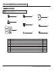
Pre-Installation (continued) HARDWARE INCLUDED NOTE: Hardware shown to actual size unless noted otherwise in the table below. DD AA GG BB EE HH CC FF Part Description II Quantity AA Blade attachment hardware (3/16 in. x 17mm screws and lock washer) BB Plastic wire nut 3 CC Balance kit (not to scale) 1 DD Mounting bracket screws (preassembled) (3/16 in. x 1/2 in.
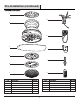
Pre-Installation (continued) PACKAGE CONTENTS A G LO HI W B MED H C OFF I D J E K F Quantity Part A Mounting bracket 1 G Receiver 1 B Fan motor assembly 1 H Remote control 1 C Blades 3 I Remote control holder 1 D Light kit mounting plate 1 J 100W halogen bulb 1 E Light kit plate 1 K 12V MN21/A23 battery 1 F Glass shade 1 Part Description 6 Description Quantity
Installation MOUNTING OPTIONS WARNING: To reduce the risk of fire, electric shock, or personal injury, mount the fan to an outlet box marked acceptable for fan support using the screws provided with the outlet box. An outlet box commonly used for the support of lighting fixtures may not be acceptable for fan support and may need to be replaced. If in doubt, consult a qualified electrician.
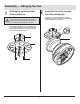
Assembly — Hanging the Fan 1 2 Attaching the mounting bracket to the electrical box □ WARNING: To reduce the risk of fire, electric shock or other personal injury, mount the fan only to an outlet box or supporting system marked acceptable for fan support and use the mounting screws provided with the outlet box. □ Attach the mounting bracket (A) to the outlet box (JJ) (not included) with the two screws and washers (XX) provided with the outlet box (JJ).
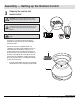
Assembly — Setting up the Remote Control 3 Preparing the receiver and remote control WARNING: To avoid possible electrical shock, ensure electricity is turned off at the main fuse box before wiring. H CAUTION: The frequency switches on the receiving unit are covered with a rubber cover. Remove the rubber cover, and then replace it after making any changes to the frequency switches. G CAUTION: Do not use this fan with a wall light dimmer switch.
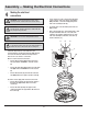
Assembly — Making the Electrical Connections 4 Making the electrical connections WARNING: To avoid possible electrical shock, ensure electricity is turned off at the main fuse box before wiring. WARNING: Check to see that all connections are tight, including ground, and that no bare wire is visible at the wire nuts, except for the ground wire. CAUTION: Do not use with a wall light dimmer switch.
Assembly — Finishing the Fan Motor Installation 5 Attaching the fan motor assembly to the mounting bracket □ Loosen two of the four mounting bracket screws (DD) from the mounting bracket (A), and remove the other two screws (DD). □ Remove the fan motor assembly (B) from the mounting bracket (A) hook, and engage the key holes with the two mounting bracket screws (DD) previously loosened.
Assembly — Attaching the Fan Blades 7 Fastening the blade assemblies to the motor B WARNING: To reduce the risk of personal injury, do not bend the blade arms while installing, balancing the blades (C), or cleaning the fan. Do no insert foreign objects between rotating fan blades (C). □ Insert a blade (C) through one of the slots in the bottom band. □ Align the holes in the blade with the three holes in a blade support plate (GG). The raised holes in the blade support plate (GG) should face down.
Assembly — Installing the Light Kit 8 Attaching the light kit mounting plate to the mounting ring 9 □ Remove one of three mounting ring screws (HH) from the mounting ring (YY) and loosen the other two screws. (Do not remove) □ Place the key holes in the light kit mounting plate (D) over the two screws (HH) previously loosened from the mounting ring (YY), turn the light kit mounting plate (D) until it locks in place at the narrow section of the key holes.
Assembly — Installing the Light Kit (continued) 10 Finishing the light kit assembly and mounting the glass shade WARNING: Before starting installation, disconnect the power by turning off the circuit breaker or removing the fuse at the fuse box. Turning power off using the fan switch is not sufficient to prevent electric shock. □ Install the 100 Watt halogen bulb (J) (included).
Operation REMOTE CONTROL OPERATING INSTRUCTIONS Install a 12V MN21/A23 battery (K) (included) in-to the remote control (H). To prevent damage to the remote control (H), remove the battery (K) if not used for long periods. □ Restore power to the ceiling fan and test for proper operation. H "HI , MED, LOW " buttons: These three buttons are used to set the fan speed as follows: LOW = Low speed, MED = Medium speed, and HI = High speed. K "OFF" button: This button turns the fan off.
Operation (continued) REVERSE SWITCH OPERATING INSTRUCTIONS The reverse switch is located on the surface of the switch housing. This switch controls directions: forward (switch left) or reverse (switch right). NOTE: Wait for the fan to stop before reversing the direction of the blade rotation. Warm weather - (Counterclockwise Direction) A downward air flow creates a cooling effect. This allows you to set your air conditioner on a warmer setting without affecting your comfort.
Troubleshooting WARNING: Make sure the power is off at the electrical panel box before you attempt any repairs. Refer to step 4 “Making the electrical connections” on page 10. Problem The fan will not start. The fan sounds noisy. The remote control is not working. Solution □ Check main and branch circuit fuses or breakers. □ Check line wire connections to the fan and switch wire connections in the switch housing.
Service Parts A E AA BB B F CC G LO HI W DD MED H OFF EE FF C I GG J HH D K Description Part Description A Mounting bracket AA B Fan motor assembly C 3 blades D Light kit mounting plate CC E Light kit plate DD Mounting bracket screws (3/16 in. x 1/2 in. screws F Glass shade G Receiver EE Remote control holder mounting screws H Remote control FF Remote control holder plugs Part Blade attachment hardware (3/16 in.
Questions, problems, missing parts? Before returning to the store call Hampton Bay Customer Service 8 a.m. - 6 p.m., EST, Monday-Friday 1-800-527-0998 HAMPTONBAY.COM Retain this manual for future use.