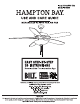
Item #1002 586 542 Model #14600 HAMPTON BAY. USE AND CARE GUIDE MENAGE LED 52 INCH CEILING FAN EASY STEP-BY-STEP 3D INSTRUCTIONS Download the Free Interactive App Google Play Leers E Questions, problems, missing parts? Before returning to the store call Hampton Bay Customer Service 8 a.m. 7 p.m., EST, Monday-Friday, 9am. 6 p.m, EST, Saturday WOLVERHAMPTON NORTHAMPTON THANK YOU We appreciate the trust and confidence you have placed in Hampton Bay through the purchase of this ceiling fan.
Table of Contents Table of Contents senses senna Safety Information... Warranty Pr-installation . Specifications Tools Required .. Hardware Included Package Contents .
Safety Information | Safety Information o o Read and save these Instructions. Ta traducer the risk of electric shock, ensure electricity has been turned off at the circuit breaker or fuse box before beginning. All wiring must be In accordance with the National Electrical Code “EXPANSION 70-1999” and local electrical codes. Electrical Installation should be performed by a qualified licensed electrician.
Warranty We warrant the fan motor to be free from defects In workmanship and material present at time of shipment from the factory for a period of Lifetime after the date of purchase by the original purchaser. We also warrant that all other fan parts, excluding any glass or acrylic blades, to be free from defects In workmanship and material at the ime of shipment from the factory for a period of ene year after the date of purchase by the original purchaser.
Pr-Installation (continued) HARDWARE INCLUDED NOTE: Hardware shown ia actual size uni ass nosed otherwise In the table below. =.
Pr-Installation (continued) PACKAGE CONTENTS Pant Description Quantity Part Description Quantity A Fan blade 5 G Coupling cover 1 B Mounting bracket 1 H Fan motor assembly 1 C Canopy 1 | Blade arm 5 D Canopy cover 1 J 17W LED assembly 1 E Hanger ball (reassembled) 1 K Glass 1 F Down rod (reassembled) 1
Installation MOUNTING OPTIONS 'WARNING: To traduces the risk of firs, electrical shook, or personal injury, mount the fan 1o an outlet box marked ‘acceptably for fan support using the screws provided with the outlet box. An outset box commonly used for the support of lighting fixtures may nat ba acceptable for fan support and may need to be replaced. If In doubt, consult a qualified electrician.
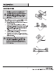
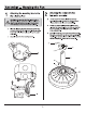
Assembly — Hanging the Fan Attaching the mounting bracket to the electrical box WARNING: Ta reduce the risk of fire, electric shock, or ‘other personal injury, mount the fan only to an outset box or supporting stern marked acceptable for fan support and 13a the mounting scows provided with the outlet box. o Place the slots from mounting bracket (B) over the two screws provided with the outlet box. Slide the mounting bracket (B) until It locks In place at the narrow section of the slots.
Assembly — Hanging the Fan (continued) 3 o Attaching the coupling cover, canopy cover, and canopy to the down rod Slip the coupling cover (6), canopy cover {D), and canopy {C) onto the down rod (F). Carefully reinstall the hanger ball (E) onto the down rod (F}, and ensure that the cross pin {EE} Is In the correct position, the set screws (HH) are tight, and the wires are not twisted.
Assembly — Hanging the Fan (continued) 5 Making the electrical connections electricity Is Tu mad off at the cultural breaker or main fuse box WARNING: To avoid possible statistical shock, ensure the A before wiring. Including the grounding, and that no bars wire is visible at the A WARNING: Hack tn ses that all connections we tight, wire nuts, except for the ground wire. Follow the steps below to connect the fan to your house supply wires.
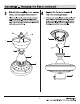
Assembly — Hanging the Fan (continued) 6 Securing the fan motor assembly to the mounting bracket o Remove one screw (JJ) from the mounting bracket (B) and loosen the other screw (J.J) approximately 1/4 tum. o Carefully raise the canopy (C) up to the mounting bracket (B), and ensure the loosened screw (JJ) Is Inserted Into the key hole on the canopy (C). Rotate the canopy {C) clockwise. 0 Secure the canopy (C) by replacing the screw (JJ) previously removed and tightening the screw (JJ) previously loosened.
Assembly — Attaching the Fan Blades Fastening the blade assemblies to the fan motor assembly WARNING: Failure to properly seat the blades (A) on the blade arms () and engage In the locking mechanistic} could result in the fun blades (A) loosening red possibly falling.
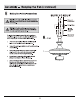
Assembly — Installing the Light Kit 9 Attaching the 17W LED Assembly to the Fan o Disassemble the switch box cover (TT) by removing the three screws (KK) on the switch box (UU) o While holding the 17W LED assembly (J) under your fan, snap together the wire connection plugs (WV). 0 Carefully push all wires back into the switch box install the 17W LED assembly (J) onto the switch box (UU) with the three screws (KK) removed previously and securely tighten all screws.
Assembly — Installing the Light Kit (continued) 1 0 Installing the glass shade 0 Remove the rubber washer (LL), metal washer (MM), hex nut (NN), cap(00) and finial(PP) from the 17W LED assembly (J). O Place the glass shade (K) over the 17W LED assembly (J) stem, and secure with the rubber washer (LL), metal washer (MM), hex nut (NN), cap{00} and finial(PP). De not over-tighten. oO Attach the pull chain fobbing) to the chain on the light kit assembly.
Operation Tum on the power and check the operation of your fan There are two pull chains used to operate your fan. The 3-speed pull chain controls the fan speed as follows: 1 pull High, 2 pulls Medium, 3 pulls Low, and 4 pulls Off. H The light kit pull chain tums the light kit "ON" or "OFF." REVERSE FUNCTION BUTTON OPERATING INSTRUCTIONS The revers switch(WW) is located on the surface of the switch housing. This switch controls directions: forward (switch down ) or reverse (switch up).
Care and Cleaning Do not Check the support connections, brackets, and blade attachments twice a year. Ensure they are secure. Because of the fan's natural movement, some connections may become loose over time. It is not necessary to remove the fan from the ceiling. Clean your fan periodically. Use only a soft brush or lint-free cloth to avoid scratching the finish. The plating Is sealed with a lacquer to minimize discoloration or famishing.
Service Parts [Ne =m Spm all ® A OU——cc Qaz = wa E Sum HH Part | Description Part | Description A | Fan blade AA | Blade screw B | Mounting bracket BB | Blade am screw CG | Canopy CC | Balance kit D | Canopy cover DD | Wire nuts E | Hanger ball (reassembled) EE | Cross pin F | Down rod (reassembled) FF | Hitch pin G | Coupling cover GG | Lock pin H | Fan motor assembly HH | Hanger ball set screw | | Blade aim Il | Fan motor assembly coupling set screw J | KNOWLEDGE assembly JJ | Mounting bracket screw (reas
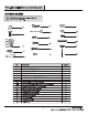
SPECIFICATIONS Airflow Cubic _ =i || ENERGY GUIDE J Estimated Avow Downtrodden* “$ Energy Cost 3,285 High 4,417 a Tate Medium 3,049 ‘Coat Range of Similar Modal (15° 84) Terr Low 2,003 | [ Srcivmemmemnn Energy Une: 39 Watts. Sao vein boo, re HAMPTON BAY. Questions, problems, missing parts? Before returning to the store call Hampton Bay Customer Service 8am. 7 p.m., EST, Monday-Friday, 9am. 6 p.m, EST, Saturday WOLVERHAMPTON NORTHAMPTON Retain this manual for future use.