Item #1002 586 860 Model #14601 USE AND CARE GUIDE MENAGE LED 52 INCH CEILING FAN Questions, problems, missing parts? Before returning to the store, call Home Decorators Collection Customer Service 8 a.m. - 6 p.m., EST, Monday-Friday 1-800-HD-HAMPTON HAMPTONBAY.
Table of Contents Table of Contents ..........................................................2 Safety Information .........................................................3 Warranty .........................................................................4 Pre-installation .............................................................. 4 Specifications .......................................................................... 4 Tools Required .................................................................
Safety Information □ Read and save these instructions. □ To reduce the risk of electric shock, ensure electricity has been turned off at the circuit breaker or fuse box before beginning. □ All wiring must be in accordance with the National Electrical Code “ANSI/NFPA 70-1999” and local electrical codes. Electrical installation should be performed by a qualified licensed electrician. □ The outlet box and support structure must be securely mounted and capable of reliably supporting a minimum of 35 lbs.
Warranty We warrant the fan motor to be free from defects in workmanship and material present at time of shipment from the factory for a period of lifetime after the date of purchase by the original purchaser. We also warrant that all other fan parts, excluding any glass or acrylic blades, to be free from defects in workmanship and material at the time of shipment from the factory for a period of one year after the date of purchase by the original purchaser.
Pre-Installation (continued) HARDWARE INCLUDED NOTE: Hardware shown to actual size unless noted otherwise in the table below.
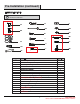
Pre-Installation (continued) PACKAGE CONTENTS G H I A B J C D K Part Description Quantity 5 Part Mounting bracket 1 H C Canopy 1 D E Canopy cover 1 1 I J A Fan blade B F G K 1 6 Description Coupling cover Quantity 1 Fan motor assembly Blade holder 1 5 17W LED assembly Glass 1 1
Installation MOUNTING OPTIONS WARNING: To reduce the risk of fire, electric shock, or personal injury, mount the fan to an outlet box marked acceptable for fan support using the screws provided with the outlet box. An outlet box commonly used for the support of lighting fixtures may not be acceptable for fan support and may need to be replaced. If in doubt, consult a qualified electrician.
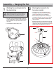
Assembly — Hanging the Fan 1 2 Attaching the mounting bracket to the electrical box WARNING: To reduce the risk of fire, electric shock, or other personal injury, mount the fan only to an outlet box or supporting system marked acceptable for fan support and use the mounting screws provided with the outlet box. □ □ Place the slots from mounting bracket (B) over the two screws provided with the outlet box. Slide the mounting bracket (B) until it locks in place at the narrow section of the slots.
Assembly — Hanging the Fan (continued) 3 □ 4 Attaching the coupling cover, canopy cover, and canopy to the downrod □ Slip the coupling cover (G), canopy cover (D), and canopy (C) onto the downrod (F). Carefully reinstall the hanger ball (E) onto the downrod (F), and ensure that the cross pin (EE) is in the correct position, the set screws (HH) are tight, and the wires are not twisted.
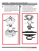
Assembly — Hanging the Fan (continued) 5 Making the electrical connections WARNING: To avoid possible electrical shock, ensure the electricity is turned off at the circuit breaker or main fuse box before wiring. WARNING: Check to see that all connections are tight, including the ground, and that no bare wire is visible at the wire nuts, except for the ground wire. Follow the steps below to connect the fan to your house supply wires.
Assembly — Hanging the Fan (continued) 6 Securing the fan motor assembly to the mounting bracket □ Remove one screw (JJ) from the mounting bracket (B) and loosen the other screw (JJ) approximately 1/4 turn. □ Carefully raise the canopy (C) up to the mounting bracket (B), and ensure the loosened screw (JJ) is inserted into the key hole on the canopy (C). Rotate the canopy (C) clockwise.
Assembly — Attaching the Fan Blades 7 8 Fastening the blade assemblies to the fan motor assembly □ Loose the fiver screws and remove the five plastic blocks from WARNING: Failure to properly seat the blades (A) on the blade arms (I) and engage in the locking mechanism(SS) could result in the fan blades (A) loosening and possiblyfalling. the fan motor assembly (G) before attaching the blade holder (I) to the fan motor assembly (G). Discard the plastic blocks and the five screws.
Assembly — Installing the Light Kit 9 Attaching the 17W LED Assembly to the Fan □ Disassemble the switch box cover (TT) by removing the three screws (KK) on the switch box (UU) □ While holding the 17W LED assembly(J) under your fan, snap together the wire connection plugs (VV). □ Carefully push all wires back into the switch box (UU),then install the 17W LED assembly (J) onto the switch box (UU) with the three screws (KK) removed previously and securely tighten all screws.
Assembly — Installing the Light Kit (continued) 10 Installing the glass shade □ Remove the rubber washer (LL), metal washer (MM), hex nut (NN), cap(OO) and finial(PP) from the 17W LED assembly (J). □ Place the glass shade (K) over the 17W LED assembly (J) stem, and secure with the rubber washer (LL), metal washer (MM), hex nut (NN), cap(OO) and finial(PP). Do not over-tighten. J K LL MM NN OO PP QQ 14 HAMPTONBAY.COM Please contact 1-800-HD-HAMPTON for further assistance.
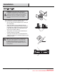
Operation Turn on the power and check the operation of your fan.There are two pull chains used to operate your fan. The 3-speed pull chain controls the fan speed as follows: 1 pull- High, 2 pulls- Medium, 3 pulls- Low, and 4 pulls- Off. G The light kit pull chain turns the light kit "ON" or "OFF." WW REVERSE FUNCTION BUTTON OPERATING INSTRUCTIONS The reverse switch(WW) is located on the surface of the switch housing(UU). This switch controls directions: forward (switch down ) or reverse (switch UP ).
Care and Cleaning Do □ Do not Check the support connections, brackets, and blade attachments twice a year. Ensure they are secure. Because of the fan’s natural movement, some connections may become loose over time. It is not necessary to remove the fan from the ceiling. □ Clean your fan periodically. Use only a soft brush or lint-free cloth to avoid scratching the finish. The plating is sealed with a lacquer to minimize discoloration or tarnishing.
Troubleshooting WARNING: Ensure the power is off at the electrical panel box before you attempt any repairs. Refer to the section “Making the Electrical Connections” on page 11. Problem The fan will not start. The fan sounds noisy. The fan wobbles. Solution □ Check main and branch circuit fuses or breakers. □ Check line wire connections to the fan and switch wire connections in the switch housing.
Service Parts G AA II JJ BB KK H A LL I CC MM DD NN EE OO B C J D FF PP K GG QQ HH Part Description Part Description A Fan blade AA B Mounting bracket BB Blade screw Blade holder screw C Canopy CC Balance kit D Canopy cover DD Wire nuts E EE F FF Cross pin Hitch pin G H Coupling cover J Fan motor assembly Blade holder 17W LED assembly K Glass I GG HH 18 Lock pin Hanger ball set screw II Fan motor assembly coupling set screw JJ KK Mounting bracket screw
SPECIFICATIONS 4,417 3,049 2,003 11 3,285 85 39 4.5 Questions, problems, missing parts? Before returning to the store, call Home Decorators Collection Customer Service 8 a.m. - 6 p.m., EST, Monday-Friday 1-800-HD-HAMPTON HAMPTONBAY.COM Retain this manual for future use.