
Instructions / Assembly
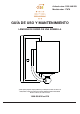

Installation
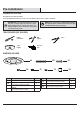
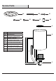
EE
AA
FF
C
GG
BB
CC
AA
DD
AA
C
5
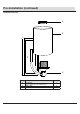
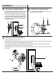
□ Unscrew the two cap nuts (GG) from the support screws (long)
(BB). Remove the mounting bracket (AA) from the canopy of
xture body (C), and keep the cap nuts (GG) for later use.
□ Loosen the hex nuts (DD) on the support screws (long) (BB)
and adjust the support screws (long) (BB) so that they extend
long enough to protrude through the canopy of the xture
body (C), then secure the support screws (long) (BB) in place
using the hex nuts (DD).
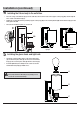
□ Strip 3/4 in. of insulation from the wire ends.
□ Connect the black wire from the xture body (C) to the black wire from the outlet box, and the white wire from the xture body (C) to
the white wire from the outlet box. Twist the stripped ends together with pliers.
□ Loop the bare copper grounding wire from the xture body (C) under the head of the green ground screw (EE) on the mounting
bracket (AA), and connect it to the grounding conductor from the supply circuit.
□ Cover the wires with wire connectors (FF). Tape the wire connectors (FF) and wires together, and carefully position all wires inside
the outlet box.
□ Fasten the mounting bracket (AA) onto the outlet box using
two outlet box screws (short) (CC).
1
Preparing the mounting bracket
3
Making the electrical connections
2
Installing the mounting bracket