Item # 1003132247 # 1003054957 # 1003063474 # 1003063475 Model # 18-751-48 # 18-751-48-Y # 18-751-93-Y # 18-751-204-Y USE AND CARE GUIDE COMPACT INFRARED FIREPLACE IMPORTANT INSTRUCTIONS PLEASE READ THIS MANUAL BEFORE INSTALLING AND USING APPLIANCE WARNING! C US IF THE INFORMATION IN THIS MANUAL IS NOT FOLLOWED EXACTLY, AN ELECTRICAL SHOCK OR FIRE MAY RESULT CAUSING PROPERTY DAMAGE, PERSONAL INJURY OR LOSS OF LIFE. INSTALLER: Leave this manual with the appliance.
Table of Contents Table of Contents. . . . . . . . . . . . . . . . . . . . . . . . . . . . . . . . . . . . . 2 Safety Information. . . . . . . . . . . . . . . . . . . . . . . . . . . . . . . . . . . . 3 Warranty . . . . . . . . . . . . . . . . . . . . . . . . . . . . . . . . . . . . . . . . . . . 4 Pre-Assembly . . . . . . . . . . . . . . . . . . . . . . . . . . . . . . . . . . . . . . . 5 Planning Assembly. . . . . . . . . . . . . . . . . . . . . . . . . . . . . . . . . . 5 Tools Required . . . . . . . . .
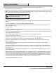
Safety Information Please read and understand this entire manual before attempting to assemble, operate or install the product. □□ Read all instructions before using this appliance. □□ This appliance is hot when in use. To avoid burns, do not let bare skin touch hot surfaces. If provided, use handles when moving this appliance. Keep combustible materials, such as furniture, pillows, bedding, papers, clothes and curtains at least 3 ft.
Warranty 1-YEAR WARRANTY WHAT IS COVERED The manufacturer warrants that your new electric fireplace is free from manufacturing and material defects for a period of one year from date of purchase, subject to the following conditions and limitations. Variations in actual wood color and finishes which may result from natural characteristics of the wood, such as grain patterns, mineral streaks and the like, are not considered defects.
Pre-Assembly PLANNING ASSEMBLY To avoid scratching the finish, assemble the product on a soft, non-abrasive surface, such as carpet or cardboard. Assembly of this product may require more than one person. TOOLS REQUIRED Phillips screwdriver HARDWARE INCLUDED NOTE: Hardware not shown to actual size.
Pre-Assembly (continued) PACKAGE CONTENTS A E F G D F C H K E M P P N J L B Part Description Quantity Part Description Quantity A Top Panel 1 H Left Side Panel 1 B Base Panel 1 J Right Side Panel 1 C Media Shelf 1 K Left Trim 1 D Back Panel 1 L Right Trim 1 E Upper Side Panel 2 M Top Trim 1 F Upper Front Panel 2 N Base Trim 1 G Door 1 P Support Panel 2 6
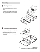
Assembly connectors 1 Attaching AA □□ Locate the left trim (K), right trim (L), top trim (M), and base trim (N) and place on soft surface to protect the finish. KK □□ Attach five connectors (KK) to left trim (K), right trim (L), top trim (M), and base trim (N) by turning the five bolts (AA) clockwise through the connector. Do not strip the bolts (AA) by overtightening.
Assembly (continued) the base trim to base panel 3 Attaching AA □□ Locate the base panel (B) and place on a soft surface to protect the finish. □□ Attach the base trim (N) to the base panel (B) by turning four bolts (AA) clockwise through the connectors. Do not trip the bolt (AA) but overtightening. □□ Attach the two support panels (P) to the base panel (B) turning four bolts (AA) clockwise through the connector. Do not strip the bolts (AA) by overtightening.
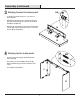
Assembly (continued) side panels to base 5 Attaching □□ Insert four wood dowels (BB) into the unthreaded holes in the base (B). J □□ Line up the four wood dowels (BB) in the base (B) with the unthreaded holes in the left and right side panels. H □□ Press left and right side panels down until flush. □□ Insert four bolts (AA) into the connectors on the side panels and turn clockwise. Do not strip the bolts (AA) by overtightening.
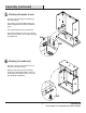
Assembly (continued) 7 A ttaching front and side panels □□ Locate the upper side panels (E) and place on a soft surface to protect the finish. □□ Insert two bolts (AA)into the connectors on the upper side panels (E) and turn clockwise. Do not strip the bolts (AA) by overtightening. AA F x2 E x2 ttaching front and side panels to 8 Amedia shelf E □□ Insert four wood dowels (BB) into the unthreaded holes in the media shelf (C).
Assembly (continued) 9 P reparing the top panel □□ Locate the top panel (A) and place on a soft surface to protect the finish. □□ Line chain (DD) holes up with holes located on bottom of top panel (A). Attach chain (DD) to top panel (A) by inserting two chain screws (EE) and turning clockwise. Do not strip the screws by overtightening. A EE □□ Attach magnetic catch (HH) to the top panel (A) by inserting four catch screws (JJ) and turning clockwise. Do not strip the screws (JJ) by overtightening.
Assembly (continued) 11 A ttaching the back panels □□ Locate the back panel (D) and line them up to the back of the media console with the finished side facing in. □□ Insert and tighten ten back panel screws (CC) to attach the back panel (D) the media console. D □□ Do not strip the screws (CC) by overtightening. CC 12 A ttaching hardware onto the doors GG □□ Locate the cabinet door (G) and place on a soft surface to protect the finish.
Assembly (continued) 13 A ttaching the media door □□ Line up the hinges in door (G) with the hinge plates on the media shelf (C). □□ Tighten the screws to attach the hinges to the hinge plates. Do not strip the screws by overtightening. G 14 A ttaching the chain □□ Attach the chain from the inside of the top panel (A) to the door (G) inserting two chain screws (EE) and turning clockwise. Do not strip the chain screws (EE) by overtightening. G EE 13 HAMPTONBAY.
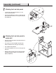
Assembly (continued) 15 I nstalling the firebox □□ Insert the firebox into the media console through the back opening. □□ Push the firebox forward through the back opening until the metal trim of the firebox in flush with the side panels (J & H). □□ Once the firebox is in position attach the two mounting brackets included with the firebox by inserting and tightening six screws through the mounting brackets into the media console. Do not strip the screws by overtightening.
Assembly (continued) 16 Anti-tip Device Installation LL Wall DANGER: This product is only a deterrent. It is not a substitute for proper adult supervision. □□ Install the Anti-tip Device according to the installation instruction. WARNING: You must install the tipping restraint hardware to help revent any accidents or damage to the unit. We strongly recommend mounting this hardware to a wall stud and your unit.
Service Parts A E F G D F C H K E M P P N L J B Part Description Quantity Part Number 18-751-48 / 18-751-48-Y Espresso Finish Part Number 18-751-93-Y Cherry Finish Part Number 18-751-204-Y White Finish A Top Panel 1 20-01-018 20-01-032 20-01-046 B Base Panel 1 20-01-019 20-01-033 20-01-047 C Media Shelf 1 20-01-020 20-01-034 20-01-048 D Back Panel 1 20-01-021 20-01-035 20-01-049 E Upper Side Panel 2 20-01-022 20-01-036 20-01-050 F Upper Front Panel 2 20-01
Troubleshooting If you have any questions regarding the product, please call Hampton Bay Customer Service, 855-HD-HAMPTON, 8 a.m. –6 p.m. EST, Monday – Friday. Problem The fireplace does not operate. The power light is ON but the flame effect is not visible. The heater is not operating. There is excessivee noise when the heater is operating. Possible Cause Solution □□ The fireplace is not plugged in. □□ Make sure the fireplace is plugged in to a standard 120V outlet.
Questions, problems, missing parts? Before returning to the store, call Hampton Bay Customer Service 8 a.m.-6 p.m., EST, Monday-Friday 855-HD-HAMPTON HAMPTONBAY.COM Retain this manual for future use. Manufactured by: GHP Group, Inc. • 6440 W. Howard St.
Artículo # 1003132247 # 1003054957 # 1003063474 # 1003063475 Modelo # 18-751-48 # 18-751-48-Y # 18-751-93-Y # 18-751-204-Y GUÍA DE USO Y MANTENIMIENTO CHIMENEA POR INFRARROJOS COMPACTA INSTRUCCIONES IMPORTANTES POR FAVOR LEE ESTE MANUAL ANTES DE INSTALAR Y USAR ESTE ELECTRODOMÉSTICO ¡ADVERTENCIA! C US SI LA INFORMACIÓN EN ESTE MANUAL NO SE SIGUE EXACTAMENTE, PUEDE PRODUCIRSE UNA DESCARGA ELÉCTRICA O INCENDIO, LO QUE PUEDE CAUSAR DAÑOS A LA PROPIEDAD, LESIONES PERSONALES O LA MUERTE.
Índice Tabla de contenido . . . . . . . . . . . . . . . . . . . . . . . . . . . . . . . . . . 20 Información de Seguridad. . . . . . . . . . . . . . . . . . . . . . . . . . . . . 21 Garantía. . . . . . . . . . . . . . . . . . . . . . . . . . . . . . . . . . . . . . . . . . . 22 Pre-ensamblaje. . . . . . . . . . . . . . . . . . . . . . . . . . . . . . . . . . . . . 23 Planificación del ensamblaje. . . . . . . . . . . . . . . . . . . . . . . . . 23 Herramientas necesarias. . . . . . . . . . . . . . . . . . .
Información de Seguridad Por favor lee este manual antes de instalar y usar este electrodoméstico. □□ Lea todas las instrucciones antes de usar este electrodoméstico. □□ Este electrodoméstico se calienta cuando está en uso. Para evitar quemaduras, no toques las partes calientes con la piel descubierta. Al moverlo, sujeta este electrodoméstico por las asas, si las tiene.
Garantía GARANTÍA DE 1 AÑO LO QUE ESTÁ CUBIERTO El fabricante garantiza que su nueva estufa eléctrica está libre de defectos de fabricación y materiales por un periodo de un año a partir de la fecha de compra, sujeto a las siguientes condiciones y limitaciones. Esta estufa eléctrica debe ser instalada y operada en todo momento de acuerdo con las instrucciones proporcionadas con el producto. Cualquier alteración, abuso intencionado, accidente o mal uso del producto anulará esta garantía.
Pre-ensamblaje PLANIFICACION DEL ENSAMBLAJE Para evitar rayar el acabado, ensamble este producto sobre una superficie suave no abrasiva, como una alfombra o cartones. El ensamblaje de este producto puede requerir más de una persona. HERRAMIENTAS REQUERIDAS Gafas de seguridad Desarmador Phillips PIEZAS INCLUÍDAS NOTA: Las herramientas son no mostradas en su tamaño real.
Pre-ensamblaje (continuación) CONTENIDO DEL PAQUETE A E F G D F C H K E M P P N J L B Part Description Quantity Part Description Quantity A Panel superior 1 H Panel lateral izquierdo 1 B Panel de base 1 J Panel lateral derecho 1 C Repisa multimedia 1 K Moldura izquierdo 1 D Panel trasero 1 L Moldura derecho 1 E Panel lateral superior 2 M Moldura superior 1 F Panel frontal superior 2 N Moldura base 1 G Puerta 1 P Panel de soporte 2 24
Ensamblaje de los conectores 1 Colocación AA □□ Localice la moldura izquierda (K), moldura derecha (L), moldura superior (M) y moldura base (N) y colóquelas en una superficie suave para proteger el acabado. KK □□ Coloque cinco conectores (KK) en la moldura izquierda (K), moldura derecha (L), moldura superior (M) y moldura base (N) girando los cinco tornillos (AA) en el sentido de las agujas del reloj a través de los conectores. No dañe los tornillos (AA) apretándolos demasiado.
Ensamblaje (continuación) de la moldura base 3 Cenolocación el panel base AA □□ Localice el panel base (B) y colóquelo sobre una superficie suave para proteger el acabado. □□ Fije la moldura base (N) al panel base (B) girando cuatro tornillos (AA) en el sentido de las agujas del reloj a través de los conectores. No dañe los tornillos (AA) apretándolos demasiado.
Ensamblaje (continuación) 5 olocación de los paneles C laterales en la base J □□ Inserte cuatro clavijas de madera (BB) en los orificios sin rosca en la base (B). □□ Alinee las cuatro clavijas de madera (BB) en la base (B) con los orificios sin rosca en los paneles laterales izquierdo y derecho. H □□ Presione los paneles laterales izquierdo y derecho uno contra otro firmemente hasta que estén al ras.
Ensamblaje (continuación) de los paneles 7 Colocación frontales y laterales □□ Localice los paneles laterales superiores (E) y colóquelos sobre una superficie suave para proteger el acabado. □□ Inserte dos tornillos (AA) en los conectores en los paneles laterales superiores (E) y gírelos en el sentido de las agujas del reloj. No dañe los tornillos (AA) apretándolos demasiado.
Ensamblaje (continuación) 9 P reparación del panel superior □□ Localice el panel superior (A) y colóquelo sobre una superficie suave para proteger el acabado. □□ Alinee la cadena (DD) con los orificios mirando hacia arriba, con los orificios ubicados en la parte de abajo del panel superior (A). Fije la cadena (DD) al panel superior (A) insertando dos tornillos de cadena (EE) y girándolos en el sentido de las agujas del reloj. No dañe los tornillos de cadena apretándolos demasiado.
Ensamblaje (continuación) 11 C olocación del panel trasero □□ Localice el panel trasero (D) y alinéelo a la parte trasera de la consola multimedia con la cara con acabado mirando hacia adentro. □□ Inserte y apriete diez tornillos de paneles posteriores (CC) para fijar el panel trasero (D) a la consola multimedia. D □□ No dañe los tornillos (CC) apretándolos demasiado.
Ensamblaje (continuación) 13 C olocación de la puerta multimedia □□ Alinee las bisagras en la puerta (G) con las placas de bisagra en la repisa multimedia (C). □□ Apriete los tornillos para fijar las bisagras a las placas de bisagra. No dañe los tornillos apretándolos demasiado. G 14 C olocación de la cadena □□ Fije la cadena desde la parte interior del panel superior (A) a la puerta (G) insertando dos tornillos de cadena (EE) y girándolos en el sentido de las agujas del reloj.
Ensamblaje (continuación) de la cámara 15 Instalación de combustión □□ Inserte la cámara de combustión dentro de la consola multimedia a través de la abertura posterior. □□ Empuje la cámara de combustión a través de la abertura posterior hasta que la moldura de metal de la cámara de combustión esté al ras con los paneles laterales (J y H).
Ensamblaje (continuación) 16 Instalación de dispositivo anti-tip LL Pared PELIGRO: Este producto es solo un disuasivo. No es un sustituto de supervisión apropiada de un adulto. □□ Instale el dispositivo antivuelco de acuerdo con las instrucciones de instalación. ADVERTENCIA: Debe instalar el Herraje contra Caidas para evitar accidentes o que se dañe la unidad. Recomendamos montar estos herrajes a un taco de pared y a la Unidad.
Piezas de servicio A E F G D F C H K E M P P N L J B Pieza Descripción Cant.
Resolución de fallas Si tiene preguntas respecto al producto, llame a Servicio al Cliente de Hampton Bay, al 855-HD-HAMPTON, de 8 a.m. a 6 p.m., hora local del Este de lunes a viernes. Problema La chimenea no funciona. La luz de energía está encendida pero el efecto de la llama no es visible. El calefactor no está funcionando. Causa posible □□ La chimenea no está enchufada. □□ Asegúrese de que la chimenea esté enchufada en un tomacorriente estándar de 120V.
¿Preguntas, problemas o piezas faltantes? Antes de regresar a la tienda, llama al Servicio al Cliente de Hampton Bay de lunes a viernes entre 8 a.m. y 6 p.m., (hora del Este de E.E. U.U.) 855-HD-HAMPTON HAMPTONBAY.COM Conserva este manual para uso en el futuro. Fabricado por: GHP Group, Inc. • 6440 W. Howard St.