Item # 1003132247 # 1003054957 # 1003063474 # 1003063475 Model # SF103-18H USE AND CARE GUIDE ELECTRIC FIREPLACE INSERT IMPORTANT INSTRUCTIONS PLEASE READ THIS MANUAL BEFORE INSTALLING AND USING APPLIANCE C US WARNING! IF THE INFORMATION IN THIS MANUAL IS NOT FOLLOWED EXACTLY, AN ELECTRICAL SHOCK OR FIRE MAY RESULT CAUSING PROPERTY DAMAGE, PERSONAL INJURY OR LOSS OF LIFE. INSTALLER: Leave this manual with the appliance. CONSUMER: Retain this manual for future reference.
Table of Contents Table of Contents. . . . . . . . . . . . . . . . . . . . . . . . . . . . . . . . . . . . . 2 Installation. . . . . . . . . . . . . . . . . . . . . . . . . . . . . . . . . . . . . . . . . . 9 Safety Information. . . . . . . . . . . . . . . . . . . . . . . . . . . . . . . . . . . . 3 Operation. . . . . . . . . . . . . . . . . . . . . . . . . . . . . . . . . . . . . . . . . . 10 Warranty . . . . . . . . . . . . . . . . . . . . . . . . . . . . . . . . . . . . . . . . . . . 6 Maintenance.
Safety Information Please read and understand this entire manual before attempting to assemble, operate or install the product. □□ Read all instructions before using this appliance. □□ This appliance is hot when in use. To avoid burns, do not let bare skin touch hot surfaces. If provided, use handles when moving this appliance. Keep combustible materials, such as furniture, pillows, bedding, papers, clothes and curtains at least 3 ft.
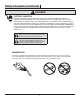
Safety Information (continued) DANGER ELECTRICAL CONNECTION A 15-Amp, 120-Volt, 60 Hz circuit with a properly grounded outlet is required. Preferably, the item will be on a dedicated circuit, as other appliances on the same circuit may cause the circuit breaker to trip or the fuse to blow when the heater is in operation. The unit comes standard with a 6 ft. (1.8 m) long three wire cord, exiting the right side of the item. Plan the installation to avoid the use of an extension cord.
Safety Information (continued) REMOTE CONTROL This device complies with Part 15 of the FCC Rules. Operation is subject to the following two conditions: (1) this device may not cause harmful interference, and (2) this device must accept any interference received, including interference that may cause undesired operation. Warning: Changes or modifications to this unit not expressly approved by the party responsible for compliance could void the user’s authority to operate the equipment.
Warranty 1-YEAR WARRANTY WHAT IS COVERED The manufacturer warrants that your new electric fireplace is free from manufacturing and material defects for a period of one year from date of purchase, subject to the following conditions and limitations. This electric fireplace must be installed and operated at all times in accordance with the instructions furnished with the product. Any alteration, willful abuse, accident, or misuse of the product shall nullify this warranty.
Pre-Installation PLANNING INSTALLATION To avoid scratching the finish, assemble the product on a soft, non-abrasive surface, such as carpet or cardboard. Assembly of this product may require more than one person. TOOLS REQUIRED Safety Goggles Phillips screwdriver HARDWARE INCLUDED NOTE: Hardware not shown to actual size. AA BB Part Description Quantity AA Trim Pieces 3 BB Small Screws 12 7 HAMPTONBAY.COM Please contact 855-HD-HAMPTON for further assistance.
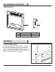
Pre-Installation (continued) PACKAGE CONTENTS A Part Description B Quantity A Fireplace Insert 1 B Infrared Remote Control 1 Installation ATTACHING FIREBOX TRIMS The firebox comes with 3 metal brackets (AA) and 12 black screws (BB). These metal brackets (AA) must be attached to all 3 sides of the firebox and 2 sides of the mantel to ensure that your firebox does not move around as you use it. All 3 trims (AA) attach to the firebox by inserting and tightening 2 screws (BB).
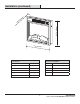
Installation (continued) ) n. 4i (12 m 8m 18.07 in. (459 mm) 5.0 18 in. (45 7 mm) Specifications Voltage Frequency Rated Power Clearance to Combustibles 120V AC Sides 2 27/64 in. (61.5 mm) 60HZ Floor 0 in. (0 mm) 1400W Top 2 in. (51 mm) Width 18 in. (457mm) Front 36 in. (914 mm) Depth 5.04 in. (128mm) Rear 25/32 in. (20 mm) Height 18.07 in. (459mm) 9 HAMPTONBAY.COM Please contact 855-HD-HAMPTON for further assistance.
Operation NOTE: When the heat function is used for the first time, a slight odor may be present. This is normal and should not occur again unless the heater is not used for an extended period of time. 1 1 4 Using the Control Panel 3 □□ Check that the heater outlet grill is not covered or obstructed in anyway, and make sure the power to the unit is switched on. □□ The fireplace can be accessed in two ways: Using the touchpad control panel, or using the multifunction remote control unit.
Operation (continued) REMOTE CONTROL INFORMATION The infrared remote control relies on a line of sight and must be pointed at the flame/screen of the fireplace to work. The remote control unit has the controls required to turn ON/OFF both the main power and the heater. If you prefer to use the touchpad control on the fireplace unit itself, open the control panel sliding cover to access the touchpad buttons. The layout of the buttons on touchpads and remote control unit can be seen on the previous page.
Maintenance (continued) DANGER Disconnect power before servicing. Any electrical re-wiring of this appliance must be done by a qualified electrician. This wiring must be done in accordance with local codes and/or in Canada with the current CSA C22.1 Canadian Electrical Code, and for US installations, the National Electrical Code ANSI/NFPA NO 70. If repairing or replacing any electrical component or wiring, the original wire routing, color coding and securing locations must be followed.
Troubleshooting If you have any questions regarding the product, please call Hampton Bay Customer Service, 855-HD-HAMPTON, 8 a.m. –6 p.m. EST, Monday – Friday. Problem Possible Cause Solution □□ The fireplace is not plugged in. □□ Make sure the fireplace is plugged in to a standard 120V outlet. □□ A circuit breaker is tripped or a fuse is blown. □□ Check additional appliances on the circuit; ideally the fireplace should be on a dedicated 15-amp circuit. □□ The ON/OFF switch is defective.
Service Parts Part Description Part # Part Description Part # 1 Fixed Plate on Fireplace SF103-18.2 11 Logset SF103-18-2 2 Fan and Heater Assembly SF103-18-4 12 PP Screen Support SF103-18-3 3 Printed Control Board EF10318G003 13 Service Window Cover SF103-18-10 4 Motor Bracket SF103-18.D.7 14 Flame PCB EF10318G004 5 Synchronous Motor SF103-18.1 15 Trim SF103-18.
Questions, problems, missing parts? Before returning to the store, call Hampton Bay Customer Service 8 a.m.-6 p.m., EST, Monday-Friday 855-HD-HAMPTON HAMPTONBAY.COM Retain this manual for future use. Manufactured by: GHP Group, Inc. • 6440 W. Howard St.
Article # 1003132247 # 1003054957 # 1003063474 # 1003063475 Modèle # SF103-18H GUIDE D'UTILISATION ET D'ENTRETIEN ENCART DE FOYER ÉLECTRIQUE INSTRUCTIONS IMPORTANTES VEUILLEZ LIRE CE MANUEL AVANT D'INSTALLER ET D'UTILISER CET APPAREIL C US AVERTISSEMENT! SI LES INFORMATIONS CONTENUES DANS CE MANUEL NE SONT PAS EXACTEMENT SUIVIES, UN CHOC ÉLECTRIQUE OU UN INCENDIE POURRAIT SURVENIR, CAUSANT DES DOMMAGES À LA PROPRIÉTÉ, DES BLESSURES OU DES PERTES DE VIE.
Table des matières Table des matières . . . . . . . . . . . . . . . . . . . . . . . . . . . . . . . . . . . 2 Installation. . . . . . . . . . . . . . . . . . . . . . . . . . . . . . . . . . . . . . . . . . 9 Mesures de sécurité . . . . . . . . . . . . . . . . . . . . . . . . . . . . . . . . . . 3 Fonctionnement. . . . . . . . . . . . . . . . . . . . . . . . . . . . . . . . . . . . . 10 Garantie. . . . . . . . . . . . . . . . . . . . . . . . . . . . . . . . . . . . . . . . . . . . 6 Maintenance. . . . .
Mesures de sécurité Veuillez lire et comprendre la totalité de ce manuel avant d'assembler, de faire fonctionner ou d'installer ce produit. □□ Lisez toutes les instructions avant d'utiliser cet appareil. □□ Cet appareil est chaud pendant l'utilisation. Pour éviter les brûlures, ne laissez pas la peau nue toucher les surfaces chaudes. Si fourni, utiliser les poignées pour déplacer l'appareil.
Information de sécurité (suite) DANGER BRANCHEMENT ÉLECTRIQUE Un circuit de 15-Amp, 120 volts, 60 Hz avec une prise correctement mise à la terre est requis. De préférence, l'élément sera sur un circuit dédié, comme les autres appareils sur le même circuit peuvent provoquer le déclenchement du disjoncteur ou de griller le fusible lorsque le chauffage est en fonctionnement. L'unité est livrée en standard avec un cordon d'alimentation de 6 pieds (1,8 m) avec trois broches, qui sort du côté droit de l'élément.
Information de sécurité (suite) TÉLÉCOMMANDE Cet appareil se conforme à l’article 15 des règles FCC. Son fonctionnement est sujet aux deux conditions suivantes : (1) cet appareil ne doit pas émettre d’interférence nuisible, et (2) cet appareil doit accepter toute interférence reçue, y compris l’interférence pouvant entraîner un fonctionnement indésirable.
Garantie GARANTIE LIMITÉE D'UN (1) AN CE QUI EST COUVERT Le fabricant garantit que votre nouveau foyer électrique est exempt de défauts de matériau et de fabrication pour une période d'un an à compter de la date d'achat, sous réserve des conditions et limitations suivantes. Ce foyer électrique doit être installé et fonctionner en tout temps conformément aux instructions fournies avec le produit. Toute altération, abus volontaire, accident ou mauvais usage du produit annulera cette garantie.
Pré-installation PLANIFICATION DE L'INSTALLATION Pour éviter d'endommager ce produit, assembler sur une surface douce, non abrasive comme du tapis ou du carton. L'assemblage de ce produit peut nécessiter plus d'une personne. OUTILS REQUIS Lunettes de sécurité Tournevis Phillips MATÉRIEL INCLUS REMARQUE : Matériel non représenté à la taille réelle. AA Pièce Description BB Quantité AA Moulures 3 BB Petite vis 12 7 HAMPTONBAY.COM Contactez le 855-HD-HAMPTON pour une assistance supplémentaire.
Pré-installation (suite) CONTENU A Pièce Description B Quantité A Encart de foyer 1 B Télécommande infrarouge 1 Installation FIXATION DES MOULURES DE LA BOÎTE DE COMBUSTION La boîte de combustion est livrée avec 3 supports en métal (AA) et 12 vis noires (BB). Ces supports en métal (AA) doivent être fixés aux 3 côtés de la boîte à combustion et aux 2 côtés du foyer pour que votre boîte de combustion ne se déplace pas quand vous l’utilisez.
Installation (suite) ) o 4p (12 m 8m 18,07 po (459 mm) 5,0 18 po (45 7 mm) Dégagement à proximité de matériaux combustibles Spécifications Côtés 2 27/64 po (61,5 mm) Plancher 0 po (0 mm) Haut 2 po (51 mm) 18 po (457mm) Devant 36 po (914 mm) Profondeur 5,04 po (128mm) Arrière 25/32 po (20 mm) Hauteur 18,07 po (459mm) Tension Fréquence Puissance nominale du dispositif de chauffage Largeur 120V AC 60HZ 1400W 9 HAMPTONBAY.
Fonctionnement 1 REMARQUE : Lorsque la fonction de chauffage est utilisé pour la première fois, une légère odeur peut être présente. Ceci est normal et ne devrait pas se produire à nouveau à moins que le chauffage ne soit pas utilisé pendant une période de temps prolongée. 1 4 3 Utilisation du panneau de commande □□ Vérifier que le gril de sortie de l'appareil de chauffage n'est pas couvert ou obstrué de quelque façon, et s'assurer que l'appareil est allumé.
Fonctionnement (suite) INFORMATIONS SUR LA TÉLÉCOMMANDE La télécommande infrarouge fonctionne avec une ligne de visée et doit être pointée sur la flamme/écran du foyer pour fonctionner. La télécommande dispose des commandes requises pour activer/ désactiver l'alimentation principale et le chauffage. Si vous préférez utiliser le pavé tactile sur le foyer, ouvrez le couvercle coulissant du panneau de commande pour accéder aux boutons du pavé tactile.
Maintenance (suite) DANGER Débrancher l'alimentation électrique avant d'effectuer les travaux d'entretien. Tout recâblage de cet appareil doit être effectué par un électricien agréé. Veillez à ce que le câblage soit effectué conformément aux codes locaux ou, au Canada, à la plus récente version du Code canadien de l’électricité, CSA C22.1 ou, dans le cas des installations aux É.-U., au code national de l’électricité, ANSI/NFPA N° 70.
Dépannage Si vous avez des questions concernant ce produit, appelez le service à la clientèle de Hampton Bay au 855-HD-HAMPTON, de 8 h à 18 h heure normale de l’Est, du lundi au vendredi. Problème Cause Possible Solution □□ Le foyer n'est pas branché. □□ S'assurer que le foyer est branché dans une prise standard de 120 V. □□ Un disjoncteur est déclenché ou un fusiblea sauté. □□ Vérifier si d’autres appareils sont alimentés par le même circuit.
Pièces de rechange Pièces Description Pièces No. Part Description Pièces No. 1 Plaque fixe sur le foyer SF103-18.2 11 Jeu de bûches SF103-18-2 2 Ventilateur et chauffage SF103-18-4 12 Support d’écran PP SF103-18-3 3 Panneau de commande imprimé EF10318G003 13 Couverture pour fenêtre de service SF103-18-10 4 Support du moteur SF103-18.D.7 5 Moteur synchrone SF103-18.
Questions, problèmes, pièces manquantes? Avant de retourner au magasin, appelez le service à la clientèle de Hampton Bay de 8h à 18h, heure normale de l'Est, du lundi au vendredi 855-HD-HAMPTON HAMPTONBAY.COM Conservez ce manuel pour un usage ultérieur. Fabriqué par : GHP Group, Inc. • 6440 W. Howard St.
Artículo # 1003132247 # 1003054957 # 1003063474 # 1003063475 Modelo # SF103-18H GUÍA DE USO Y CUIDADO INSERTO DE CHIMENEA ELÉCTRICA INSTRUCCIONES IMPORTANTES POR FAVOR, LEA ESTE MANUAL ANTES DE LA INSTALACIÓN Y USO DEL DISPOSITIVO C US ¡ADVERTENCIA! SI LA INFORMACIÓN EN ESTE MANUAL NO SE SIGUE CON EXACTITUD, PUEDE RESULTAR UN CHOQUE ELÉCTRICO O INCENDIO OCASIONANDO DAÑOS A LA PROPIEDAD, LESIONES PERSONALES O LA MUERTE. INSTALADOR: Deje este manual con el dispositivo.
Tabla de contenido Tabla de contenido . . . . . . . . . . . . . . . . . . . . . . . . . . . . . . . . . . . 2 Instalación. . . . . . . . . . . . . . . . . . . . . . . . . . . . . . . . . . . . . . . . . . 9 Información de seguridad. . . . . . . . . . . . . . . . . . . . . . . . . . . . . . 3 Operación . . . . . . . . . . . . . . . . . . . . . . . . . . . . . . . . . . . . . . . . . 10 Garantía. . . . . . . . . . . . . . . . . . . . . . . . . . . . . . . . . . . . . . . . . . . . 6 Mantenimiento. . . .
Información de seguridad Por favor, lea y comprenda este manual completo antes de intentar ensamblar, operar o instalar el producto. □□ Lea todas las instrucciones antes de usar este aparato. □□ Este dispositivo se calienta cuando está en uso. Para evitar quemaduras, no permita que la piel desnuda toque las superficies calientes. Si se proporcionan, use manijas cuando mueva este dispositivo.
Información de seguridad (continuado) PELIGRO CONEXIÓN ELÉCTRICA Se requiere un circuito de 15 Amp, 120 Voltios, 60 Hz con un tomacorriente aterrizado adecuadamente. De preferencia, el artículo estará en un circuito dedicado, ya que otros dispositivos en el mismo circuito podrían hacer que el disyuntor de circuito se active o el fusible explote cuando el calefactor esté en funcionamiento. La unidad viene estándar con un cable de tres alambres de 6 pies (1.
Información de seguridad (continuado) CONTROL REMOTO Este dispositive cumple con las reglas de Ia FCC parte 15. La operación esta sujeta a las siguientes dos condiciones: (1) Este dispositivio no puede causar interferencias perjudiciales, y (2) este dispositive debe aceptar cualquier interferencia recibida, incluyendo interferencias que pueda causar funcionamiento no deseado.
Garantía GARANTÍA DE 1 AÑO LO QUE ESTÁ CUBIERTO El fabricante garantiza que su nueva chimenea eléctrica está libre de defectos de fabricación y materiales por un periodo de un año a partir de la fecha de compra, sujeto a las siguientes condiciones y limitaciones. Esta chimenea eléctrica debe ser instalada y operada en todo momento de acuerdo con las instrucciones proporcionadas con el producto. Cualquier alteración, abuso intencionado, accidente o mal uso del producto anulará esta garantía.
Pre-instalación PLANIFICACIÓN DE LA INSTALACIÓN Para evitar rayar el acabado, ensamble este producto sobre una superficie suave no abrasiva, como una alfombra o cartones. El ensamblaje de este producto puede requerir más de una persona. HERRAMIENTAS REQUERIDAS Gafas protectoras Destornillador Phillips HERRAJE INCLUIDO NOTA : No se muestra el herraje en el tamaño real. AA Pieza Descripción BB Cantidad AA Molduras 3 BB Tornillos pequeños 12 7 HAMPTONBAY.
Pre-instalación (continuado) CONTENIDO DEL PAQUETE A Pieza Descripción B Cantidad A Inserto de chimenea 1 B Control remoto infrarrojo 1 Instalación COLOCACIÓN DE LAS MOLDURAS DE LA CÁMARA DE COMBUSTIÓN La cámara de combustión incluye 3 soportes de metal (AA) y 12 tornillos negros (BB). Estos soportes de metal deben colocarse tanto en los 3 laterales de la cámara de combustión como en los 2 laterales de la repisa para asegurar que su cámara de combustión no se desplace mientras la utilice.
Instalación (continuado) m) m 28 4 18.07 pulg. (459 mm) 5.0 (1 lg. u p 18 pulg. (4 57 mm) Espacio libre para combustibles Especificaciones Voltaje Frecuencia Capacidad nominal del calefactor Anchura 120V AC 60HZ 1400W 18 pulg. (457mm) Profundidad 5.04 pulg. (128mm) Altura 18.07 pulg. (459mm) Lados 2 27/64 pulg. (61,5 mm) Piso 0 pulg. (0 mm) Cubierta 2 pulg. (51 mm) Frente 36 pulg. (914 mm) Parte trasera 25/32 pulg. (20 mm) 9 HAMPTONBAY.
Operación NOTA: Cuando la función de calor es usada por primera vez, se puede presentar un ligero olor. Esto es normal y no debe ocurrir otra vez a menos que el calefactor no se use por largo tiempo. 1 1 4 Uso del panel de control 3 □□ Compruebe que la rejilla de salida del calefactor no esté cubierta ni obstruida en ninguna manera y asegúrese de que la energía de la unidad esté encendida.
Operación (continuación) INFORMACIÓN DEL CONTROL REMOTO El control remoto infrarrojo depende de una línea de visión y debe ser apuntado a la llama/rejilla para que funcione. La unidad de control remoto tiene los controles requeridos para ENCENDER/APAGAR tanto la energía principal como el calefactor. Si prefiere el control de teclado táctil en la unidad de la chimenea, abra el panel de control deslizándo la cubierta para acceder a los botones del teclado táctil.
Mantenimiento (continuación) PELIGRO Desconecte la energía antes de dar servicio. Cualquier renovación de cableado de este dispositivo debe ser hecho por un electricista calificado. Este cableado debe ser hecho de acuerdo con códigos locales y/o en Canadá con el Código Eléctrico Canadiense actual CSA C22.1 y para instalaciones en los EE. UU., el Código Eléctrico Nacional ANSI/NFPA NO 70.
Solución de Problemas Si tienes alguna pregunta referente al producto, por favor comunícate con el Servicio al Cliente de Hampton Bay al 855-HD-HAMPTON, de 8 a.m. a 6 p.m. de lunes a viernes entre las 8 a.m. y 6 p.m., (hora del Este de EE. UU.) Problema La chimenea no funciona. Causa posible □□ La chimenea no está enchufada. □□ Asegúrese de que la chimenea esté enchufada en un tomacorriente estándar de 120V. □□ Un disyuntor de circuito se ha activado o un fusible ha explotado.
Piezas de repuesto Pieza Descripción Pieza # Pieza Descripción Pieza # 1 Placa fija en la chimenea SF103-18.2 11 Juego de leños SF103-18-2 2 Ensamblaje del ventilador y calefacción SF103-18-4 12 Soporte de la pantalla PP SF103-18-3 3 Panel de control impreso EF10318G003 13 Tapa de la ventana de servicio SF103-18-10 4 Soporte del motor SF103-18.D.7 14 Panel control impreso de la llama EF10318G004 5 Motor sincrónico SF103-18.1 15 Moldura SF103-18.
¿Preguntas, problemas o piezas faltantes? Antes de regresar a la tienda, llama al Servicio al Cliente de Hampton Bay de lunes a viernes entre 8 a.m. y 6 p.m., (hora del Este de E.E. U.U.) 855-HD-HAMPTON HAMPTONBAY.COM Conserva este manual para uso en el futuro. Manufactured by: GHP Group, Inc. • 6440 W. Howard St.