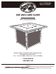
Item #:1003369086 Model #:TRS40G2 USE AND CARE GUIDE River Crossing Firepit Set Questions, problems, missing parts? Before returning to the store, call Hampton Bay Customer Service. 8 a.m. - 7 p.m., EST, Monday - Friday, 9 a.m. - 6 p.m., EST, Saturday 1-855-HD-HAMPTON HAMPTONBAY.COM THANK YOU y through the purchase of this sectional set. We strive to continually create quality products designed to enhance your home.
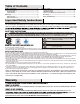
Table of Contents Table of Contents .......................................................... 2 Safety Information ............... ........................................ 2 Product Caution .................................................................... 2 Safety Warnings ............................ ........................................ 2 Warranty ........................................................................ 2 What is Covered .............................................................
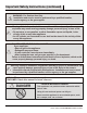
Important Safety Instructions (continued) WARNING: For Outdoor Use Only Installation and service must be performed by a qualified installer, service agency, or the gas supplier. Warning: If the information in this manual is not followed exactly, a fire or explosion may result causing property damage, personal injury, or loss of life. • Do not store or use gasoline, or other flammable vapors and liquids, in the vicinity of this or any other appliance.
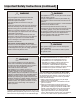
Important Safety Instructions (continued) WARNING Keep the appliance area clear and free from combustible materials, gasoline, and other flammable vapors and liquids. Solid fuels should not be burned in this gas appliance. Inspect the hose before each use of the appliance. The hose assembly must be replaced prior to the appliance being put into operation if there is evidence of excessive abrasion, wear, or if the hose is damaged. The replacement hose assembly is specified in this manual.
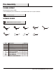
Pre-Assembly PLANNING ASSEMBLY Read all instructions before assembly. To avoid damaging this product, assemble it on a soft, non-abrasive surface such as carpet or cardboard. NOTE: More than one person may be required to assemble this product. HARDWARE INCLUDED NOTE: Hardware not shown to actual size. Part AA BB FF GG Description CC HH EE II Quantity AA BB M6x40 Bolt M6x25 Bolt 4+1 4+1 CC DD EE FF M6x15 Bolt ST4.8x16 SCREW 6+1 2+1 4MM HEX. KEY WRENCH 10MM HEX.
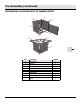
Pre-Assembly (continued) RIVER CROSSING 5PC CUSHION FIREPIT SET PACKAGE CONTENTS D A C B E G H F I Part Description Quantity A REAR FRAME 1 B FRAME A 1 C FRAME B 1 1 1 D CROSS BRACE E F G BOTTOM FRAME FRONT DOOR BTABLE TOP 1 H COVER 1 I GLASS 1 1 6
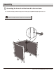
Assembly 1 Connecting the frame A and the frame B to the rear frame Fasten the frame A (B) and the frame B (C) to the rear frame (A) by using M6x40 bolts (AA). Keep the bolts loose. NOTE: Loosely tighten all the bolts using the hex wrenches (EE and FF). AA A 3 C 2 B 7 HAMPTONBAY.COM Please contact 1-855-HD-HAMPTON for further assistance.
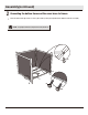
l Assembly(continued) 2 Connecting the bottom frame and the cross brace to frames Fasten the bottom frame (E) and the cross brace (D) to frames (B and C) by using M6x25 bolts (BB) and ST4.8x16 screws (DD). NOTE: Loosely tighten all the bolts using the hex wrenches (EE and FF).
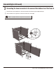
l Assembly(continued) 3 Connecting the lower connector to the corner of the bottom rim of the frame B Fasten the lower connector (GG) to the corner of the bottom rim of the frame B (C) by using M6x15 bolt (CC). Then, insert the front door (F) into the connector tab of the lower connector (GG). NOTE: Loosely tighten all the bolts using the hex wrenches (EE and FF). CC GG C E C F C F GG 9 HAMPTONBAY.COM Please contact 1-855-HD-HAMPTON for further assistance.
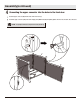
l Assembly(continued) 4 Connecting the upper connector into the holes in the front door Insert the upper connector (HH) into the holes in the front door (F). Fasten the upper connector (HH) to the frame B (C) by using M6x15 bolt (CC).Completely tighten all of the nuts and bolts. Close the doors. NOTE: Loosely tighten all the bolts using the hex wrenches (EE and FF).
l Assembly(continued) 5 Connecting the table top onto the frame assembly Place the table top (G) onto the frame assembly. Fasten them together by using M6x15 bolts (CC). Make sure that all of the bolts have been tightened completely. NOTE: Loosely tighten all the bolts using the hex wrenches (EE and FF). CC G Igniter Valve 11 HAMPTONBAY.COM Please contact 1-855-HD-HAMPTON for further assistance.
l Assembly(continued) 6 Connecting the front door and place the tank into the bottom frame Open the front door (F) and place the tank into the bottom frame (E). Secure in place by using the plastic screw.
l Assembly(continued) 7 Connecting the table top Attach the table top (G) to the tank by rotating clockwise to its connector. Caution: The Tank must face this way. 9 G Rotate Clockwise 13 HAMPTONBAY.COM Please contact 1-855-HD-HAMPTON for further assistance.
l Assembly(continued) 8 Connecting Place the glass Place the glass (I) into the steel cover. I Fire Shield Note: The fire shield on the burner system must be exposed. Note: The glass cannot be exposed over top of the steel cover surface.
Assembly(continued) 9 Connecting Place the cover onto the table top Place the cover (H) onto the table top (G) to cover the glass set. To repair any scratches on the table top, use the touch-up paint for table top (GG) provided. H G 15 HAMPTONBAY.COM Please contact 1-855-HD-HAMPTON for further assistance.
INSTRUCTIONS FOR REMOVING THE TANK 1 Removing the tank from the table top connector To remove the fuel supply hose from the tank, rotate counter-clockwise. NOTE: Close the valve tightly before removing the tank. Counter-Clockwise 9 FOR YOUR SAFETY: Surfaces of fire pit can remain extremely hot for a period after use. Allow 45 minutes to cool down before touching or moving the fire pit.
INSTRUCTIONS FOR REMOVING THE TANK 2 Removing the tank from the table top connector Remove the tank from the tank-support assembly and through the tank fastener. NOTE: To replace the tank, repeat Step 6 and Step 7 in the assembly instructions. 17 HAMPTONBAY.COM Please contact 1-855-HD-HAMPTON for further assistance.
OPERATION Switch Usage Instruction AAA OFF/Arrêt OFF/Arrêt LOW/ Min. ON/ Allu- mage ON/ Allu- HI/ Max. mage HI/ Max. 2 1 Lighting Adjusting and Shutting Down If the burner is not lit, press down the control knob and turn clockwise to the "OFF" position. Repeat step 1 after 5 minutes. When the burner is lit, press down the control knob and turn it to the desired heat output position between “LOW” and “HIGH”.
Read the following switch usage instructions for lighting and to extinguish: Step 3 Step 4 Instructions for lighting and shutting down the appliance: 1. Read instructions before lighting. 2. Press down the control knob to " LOW ", at the same time push in the ignition button and keep the button depressing for 15 seconds. 3. If the burner is not lit in 5 seconds, press down the control knob and turn clockwise to the "OFF" position. Repeat from step 2 after 5 minutes. 4.
Questions, problems, missing parts? Before returning to the store, call Hampton Bay Customer Service. 8 a.m. - 7 p.m., EST, Monday - Friday, 9 a.m. - 6 p.m., EST, Saturday 1-855-HD-HAMPTON HAMPTONBAY.COM Retain this manual for future use.