Item #1002 711 156, 1002 711 135 Model #91100, 91044 UL Model #44-MDL USE AND CARE GUIDE MIDILI 44 IN. CEILING FAN Questions, problems, missing parts? Before returning to the store call Hampton Bay Customer Service 8 a.m. - 6 p.m., EST, Monday-Friday 1-855-HD-HAMPTON HAMPTONBAY.COM To view an instructional video on how to install this product: 1. Go to www.homedepot.com and enter either the Item or Model number, found in the top right corner of the cover of this instruction manual, in the search field.
Table of Contents Table of Contents................................................................. 2 Assembly............................................................................... 7 Safety Information................................................................ 2 Operation............................................................................ 15 Warranty................................................................................ 3 Care and Cleaning................................
Warranty The supplier warrants the fan motor to be free from defects in workmanship and material present at time of shipment from the factory for a lifetime after the date of purchase by the original purchaser. The supplier also warrants that all other fan parts, excluding any glass or acrylic blades, to be free from defects in workmanship and material at the time of shipment from the factory for a period of one year after the date of purchase by the original purchaser.
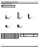
Pre-Installation (continued) HARDWARE INCLUDED NOTE: Hardware not shown to actual size.
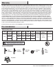
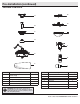
Pre-Installation (continued) PACKAGE CONTENTS G A H B C I D J E LIGHT/DIMMER GRADATEUR LUM LO BAS MED MOY HI HAUT FAN OFF ARRET VENT K TM F Part Description L Quantity Part Description Quantity F Blade 5 A Slide-on mounting bracket (inside canopy) 1 G Blade bracket 5 B Ball/downrod assembly 1 H Light Kit Fitter Assembly 1 C Canopy with canopy ring attached 1 I Glass bowl 1 D Decorative motor collar cover 1 J Receiver 1 E Fan-motor assembly 1 K Remote con
Installation MOUNTING OPTIONS WARNING: To reduce the risk of fire, electric shock or personal injury, mount to an outlet box marked “Acceptable for fan support of 35 lbs. (15.9 Kg) or less,” and use the screws provided with the outlet box. An outlet box commonly used for the support of lighting fixtures may not be acceptable for fan support and may need to be replaced. If in doubt, consult a qualified electrician.
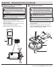
Assembly - Standard Ceiling Mount 1 2 Preparing for mounting □□ Remove the canopy ring (M) from the canopy (C) by turning □□ □□ Routing the wires □□ Route the wires exiting the top of the fan motor assembly (E) through the center of the canopy ring (M). Make sure the slots on the canopy ring (M) are on top. □□ Insert the ball/downrod (B) through the canopy (C) and slide the decorative motor collar cover (D) onto the end of the ball/downrod (B). Make sure the slots on the canopy (C) are on top.
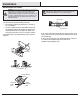
Assembly - Hanging the Fan 1 2 Attaching the mounting bracket to the outlet box Hanging the fan WARNING: The hook (JJ) is only to balance the fan while making the electrical connections. Failure to hang as shown may result in the hook (JJ) breaking, causing the fan to fall. The hook must pass from the inside to the outside of the canopy. WARNING: To reduce the risk of fire, electric shock or personal injury, mount to an outlet box marked “Acceptable for fan support of 35 lbs. (15.
Assembly - Hanging the Fan (continued) 3 4 Setting the code on the remote control and receiver Installing the receiver NOTE: The frequencies on your receiver and remote control have been preset at the factory. Before installing the receiver, make sure the dip switches on the receiver and remote control are set to the same frequency. The dip switches on the remote control are located inside the battery compartment. WARNING: To reduce the risk of fire or electric shock, remember to disconnect power.
Assembly - Hanging the Fan (continued) 5 Wiring the receiver to the household wiring WARNING: To avoid possible electrical shock, turn the electricity off at the main fuse box before wiring. If you feel you do not have enough electrical wiring knowledge or experience, contact a licensed electrician. Outlet Box in the ceiling (MM) WARNING: Each wire not supplied with this fan is designed to accept up to one 12-gauge house wire and two wires from the fan.
Assembly - Hanging the Fan (continued) 6 Wiring the fan to the receiver Outlet box in the ceiling (MM) WARNING: Remove the rubber motor stops on the bottom of the fan before installing the blades or testing the motor. Green IMPORTANT: Use the wire connecting nuts (AA) supplied with your fan. Secure the connectors with electrical tape and ensure there are no loose strands or connections.
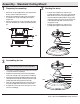
Assembly - Hanging the Fan (continued) 7 8 Wrapping the extra wire Mounting the fan-motor assembly (standard mount) WARNING: When using the standard ball/downrod mounting, the tab in the ring at the bottom of the mounting bracket must rest in the groove of the hanger ball. Failure to properly seat the tab in the groove could cause damage to the wiring. NOTE: Follow this step ONLY if you did not cut the extra length off from the wires coming from the ceiling fan to the receiver.
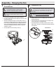
Assembly - Attaching the Fan Blades 1 2 Attaching the blades to the blade brackets Fastening the blades assemblies to the motor □□ Insert the blade / blade bracket assembly through the hole WARNING: Remove the rubber motor stops on the bottom of the fan before installing the blades or testing the motor. NOTE: Your fan features revolutionary advancements for quick and easy blade installation. This includes an alignment post and captive blade bracket screws.
Assembly - Attaching the Lights 1 Attaching the light kit fitter assembly CAUTION: To reduce the risk of electric shock, disconnect the electrical supply circuit to the fan before installing the light fixture. IMPORTANT: It is critical to attach the light kit using the quick connector. The fan will not operate unless the light kit is connected to the fan. □□ Position the light kit assembly (H) onto the fan motor assembly, □□ □□ aligning each of the four holes.
Operation A. Warm weather OPERATING YOUR FAN Your fan is equipped with a remote control to operate the fan speed and lights of your new ceiling fan. OO The speed setting for warm or cool weather depends on factors such as the room size, ceiling height, number of fans and so on. The fan is shipped from the factory with the reversing switch positioned to circulate air downward.
Care and Cleaning WARNING: Make sure the power is off before cleaning your fan. □□ Because of the fan’s natural movement, some connections may become loose. Check the support connections, brackets, and blade attachments twice a year. Make sure they are secure. It is not necessary to remove the fan from the ceiling. □□ Clean your fan periodically to help maintain its new appearance over the years.
This equipment has been tested and found to comply with the limits for a Class B digital device, pursuant to Part 15 of the FCC Rules. These limits are designed to provide reasonable protection against harmful interference in a residential installation. This equipment generates, uses and can radiate radio frequency energy and, if not installed and used in accordance with the instructions, may cause harmful interference to radio communications.