
Installation Guide
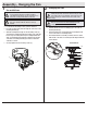


14
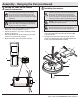
Attaching the light kit tter assembly
1
□ To attach the light kit tter assembly (H), remove the non-
slotted screw (NN) from the fan-motor assembly (E), and
loosen, but do not remove the other three screws.
□ Connect the blue wire existing the fan motor assembly (E)
with the black wire from the light kit tter assembly (H) by
engageing the molded adaptor plug.
□ Connect the white wire existing the fan motor assembly (E)
with the white wire from the light kit tter assembly (H) by
engageing the molded adaptor plug.
□ Carefully tuck all wires.
CAUTION: To reduce the risk of electric shock, disconnect
the electrical supply circuit to the fan before installing the
light xture.
NOTE: Notice the location of the fan’s slide switch. This is the
switch used to change the fan’s directional rotation. For more
information on the operation of this switch, see Operating
Your Fan on page 15.
H
E
NN
NOTE: This light kit cannot be transferred to another fan.
Assembly - Attaching the Lights
IMPORTANT: It is critical to attach the light kit using the quick
connector. The fan will not operate unless the light kit is
connected to the fan.
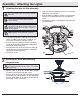
Installing the bulbs and attaching
the glass bowl
2
□ With the power off, install the LED bulb (Max. 9.5-watt,
included) by screwing into the light bulb sockets.
□ Place the glass bowl (I) into the light kit assembly (H), aligning
the three at areas on the top ange of the glass bowl (I) with
the three raised dimples in the light kit assembly. Turn the
glass bowl (I) clockwise until it stops.
I
H
L
WARNING: Do not overtighten when installing the glass shade into
the light kit assembly. Allow the glass shade to cool completely
before removing.
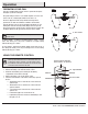
□ Position the light kit assembly (H) onto the fan motor assembly,
aligning each of the four holes.
□ Rotate the light kit assembly (H) clockwise to engage the three
mounting screws with the three key holes slots, tighten the
screws.
□ Re-install the non-slotted screw (NN) that was removed in step
1 and tighten rmly.