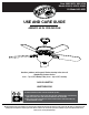
Item #XXX-XXX, XXX-XXX Model #91602, 91612, 91692 UL Model #60-ABR USE AND CARE GUIDE ASBURY 60 IN. CEILING FAN Questions, problems, missing parts? Before returning to the store call Hampton Bay Customer Service 8 a.m. - 7 p.m., EST, Monday-Friday, 9 a.m. - 6 p.m., EST, Saturday 1-855-HD-HAMPTON HAMPTONBAY.COM To view an instructional video on how to install this product: 1. Go to www.homedepot.
Table of Contents Table of Contents................................................................. 2 Assembly............................................................................... 7 Safety Information................................................................ 2 Operation............................................................................ 17 Warranty................................................................................ 3 Care and Cleaning................................
Warranty The supplier warrants the fan motor to be free from defects in workmanship and material present at time of shipment from the factory for a lifetime after the date of purchase by the original purchaser. The supplier also warrants that all other fan parts, excluding any glass or acrylic blades, to be free from defects in workmanship and material at the time of shipment from the factory for a period of one year after the date of purchase by the original purchaser.
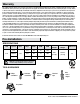
Pre-Installation (continued) HARDWARE INCLUDED NOTE: Hardware not shown to actual size.
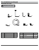
Pre-Installation (continued) PACKAGE CONTENTS A G B H C D I J E K L F Part Description Quantity Part Description Quantity F Light kit fitter assembly 1 A Slide-on mounting bracket (inside canopy) 1 G Blade 5 B Ball/downrod assembly 1 H Blade bracket 5 C Canopy with canopy ring attached 1 I Glass bowl 1 D Decorative motor collar cover 1 J LED light bulb, 9.
Installation MOUNTING OPTIONS WARNING: To reduce the risk of fire, electric shock or personal injury, mount to an outlet box marked “Acceptable for fan support of 35 lbs. (15.9 Kg) or less,” and use the screws provided with the outlet box. An outlet box commonly used for the support of lighting fixtures may not be acceptable for fan support and may need to be replaced. If in doubt, consult a qualified electrician.
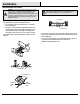
Assembly - Standard Ceiling Mount 1 2 Preparing for mounting □□ Remove the canopy ring (KK) from the canopy (C) by turning □□ Route the wires exiting the top of the fan motor assembly (E) through the center of the canopy ring (KK). Make sure the slots on the canopy ring (KK) are on top. □□ Insert the ball/downrod (B) through the canopy (C) and slide the decorative motor collar cover (D) onto the end of the ball/downrod (B). Make sure the slots on the canopy (C) are on top.
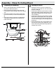
Assembly - Close-To-Ceiling Mount 1 2 Preparing for mounting □□ Remove canopy ring (KK) from the canopy (C) by turning the □□ □□ □□ □□ Remove three of the six screws and lock washers (PP) ring counter-clockwise until it unlocks. Remove the mounting bracket (A) from the canopy (C) by loosening the two canopy screws (II) located in the “L shaped” slots Remove and save the two canopy screws (JJ) in the round holes. This will enable you to remove the mounting bracket (A).
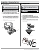
Assembly - Hanging the Fan 1 2 Attaching the mounting bracket to the outlet box Hanging the fan WARNING: The hook (MM) is only to balance the fan while making the electrical connections. Failure to hang as shown may result in the hook (MM) breaking, causing the fan to fall. The hook must pass from the inside to the outside of the canopy. WARNING: To reduce the risk of fire, electric shock or personal injury, mount to an outlet box marked “Acceptable for fan support of 35 lbs. (15.
Assembly - Hanging the Fan (continued) 3 4 Setting the code on the remote control and receiver Installing the receiver NOTE: The frequencies on your receiver and remote control have been preset at the factory. Before installing the receiver, make sure the dip switches on the receiver and remote control are set to the same frequency. The dip switches on the remote control are located inside the battery compartment. WARNING: To reduce the risk of fire or electric shock, remember to disconnect power.
Assembly - Hanging the Fan (continued) 5 Wiring the receiver to the household wiring WARNING: To avoid possible electrical shock, turn the electricity off at the main fuse box before wiring. If you feel you do not have enough electrical wiring knowledge or experience, contact a licensed electrician. Outlet Box in the ceiling (PP) WARNING: Each wire nut supplied with this fan is designed to accept up to one 12-gauge house wire and two wires from the fan.
Assembly - Hanging the Fan (continued) 6 Wiring the fan to the receiver Outlet box in the ceiling (PP) WARNING: Remove the rubber motor stops on the bottom of the fan before installing the blades or testing the motor. Green IMPORTANT: Use the wire connecting nuts (AA) supplied with your fan. Secure the connectors with electrical tape and ensure there are no loose strands or connections. Receiver (L) Receiver Antenna NOTE: The fan comes with 54 in.
Assembly - Hanging the Fan (continued) 7 8 Wrapping the extra wire Mounting the fan-motor assembly (standard mount) WARNING: When using the standard ball/downrod mounting, the tab in the ring at the bottom of the mounting bracket must rest in the groove of the hanger ball. Failure to properly seat the tab in the groove could cause damage to the wiring. NOTE: Follow this step ONLY if you did not cut the extra length off from the wires coming from the ceiling fan to the receiver.
Assembly - Hanging the Fan (continued) 9 Mounting the fan-motor assembly (close-to-ceiling mount) II A WARNING: The locking slots of ceiling canopy are provided only as an aid to mounting. Do not leave the fan assembly unattended until all four canopy screws are engaged and firmly tightened. KK C □□ Carefully unhook the fan from the mounting bracket (A) and □□ □□ □□ align the locking slots of the ceiling canopy (C) with the two screws in the mounting bracket (A).
Assembly - Attaching the Fan Blades (continued) 2 Fastening the blade assemblies to the motor □□ Fasten the blade assembly to the fan-motor assembly □□ (E) by inserting the alignment post into the slot on the bottom of the motor and tightening the blade bracket (H) screws. The blade bracket screws (QQ) are pre-installed into the blade bracket (H). Repeat this step for the remaining blade assemblies.
Assembly - Attaching the Lights (continued) 2 Installing the bulbs and attaching the glass bowl E CAUTION: Do not over tighten the hex nut. Overtightening the hex nut may cause the glass to break. □□ Remove the rubber washer (P), hex nut (Q), bottom cover (R), □□ □□ □□ □□ and finial (S) from the threaded nipple of the light kit fitter assembly (F). With power off, install the three LED light bulbs, (9.5-Watt maximum included) (L) by screwing them into the light bulb sockets.
Operation A. Warm weather OPERATING YOUR FAN Your fan is equipped with a remote control to operate the fan speed and lights of your new ceiling fan. The speed setting for warm or cool weather depends on factors such as the room size, ceiling height, number of fans and so on. YY The fan is shipped from the factory with the reversing switch positioned to circulate air downward.
Care and Cleaning WARNING: Make sure the power is off before cleaning your fan. □□ Because of the fan’s natural movement, some connections may become loose. Check the support connections, brackets, and blade attachments twice a year. Make sure they are secure. It is not necessary to remove the fan from the ceiling. □□ Clean your fan periodically to help maintain its new appearance over the years.
This equipment has been tested and found to comply with the limits for a Class B digital device, pursuant to Part 15 of the FCC Rules. These limits are designed to provide reasonable protection against harmful interference in a residential installation. This equipment generates uses and can radiate radio frequency energy and, if not installed and used in accordance with the instructions, may cause harmful interference to radio communications.
Artículo núm. XXX-XXX, XXX-XXX Modelo núm. 91602, 91612, 91692 Modelo núm. 60-ABR aprobado por UL GUÍA DE USO Y MANTENIMIENTO VENTILADOR DE TECHO ASBURY DE 1.52 M ¿Preguntas, problemas o piezas faltantes? Antes de regresar a la tienda, llama al servicio al cliente de Hampton Bay de lunes a viernes de 8 a.m. a 6 p.m. (hora estándar del Este) 1-855-HD-HAMPTON HAMPTONBAY.COM Para ver un video instructivo sobre cómo instalar este producto: 1. Ir a www.homedepot.
Tabla de contenido Tabla de contenido............................................................... 2 Ensamblaje............................................................................ 7 Información de seguridad................................................... 2 Funcionamiento.................................................................. 17 Garantía................................................................................. 3 Mantenimiento y limpieza.....................................
Garantía El proveedor garantiza de por vida, a partir de la fecha en que el comprador original lo adquiere, que el motor del ventilador no presenta defectos de fabricación ni de materiales al momento en que es enviado desde la fábrica.
Preinstalación (continuación) HERRAJES INCLUIDOS NOTA: No se muestra el tamaño real de los herrajes.
Preinstalación (continuación) CONTENIDO DEL PAQUETE A G B H C D I J E K L F Pieza Descripción Cantidad Pieza Descripción Cantidad A Soporte de montaje deslizante (dentro de la cubierta) 1 F Ensamblaje del soporte del kit de luces 1 B Ensamblaje de tubo bajante/bola 1 G Aspa 5 C Cubierta con anillo de cubierta acoplado 1 H Soporte de aspa 5 D Cubierta decorativa del collarín del motor 1 I Pantalla de vidrio 1 E Ensamblaje del motor del ventilador 1 J Bombillas LED, má
Instalación OPCIONES DE MONTAJE ADVERTENCIA: Para reducir el riesgo de incendio, descarga eléctrica o lesiones personales, instala en una caja eléctrica clasificada como “apropiada para sostener ventiladores de 15.9 kg o menos” y usa los tornillos que vienen con esta. Las cajas eléctricas utilizadas comúnmente para el soporte de lámparas pueden no servir como soporte de ventilador y tal vez deban reemplazarse. En caso de duda, consulta a un electricista calificado.
Ensamblaje - Montaje estándar en techo 1 2 Preparación para el montaje □□ Retira el aro de cubierta (KK) de la cubierta (C), girándolo en □□ □□ □□ Inserta los cables que salen por la parte superior del ensamblaje del motor del ventilador (E) a través del centro del anillo de la cubierta (KK). Asegúrate de que las ranuras del anillo de la cubierta (KK) estén en la parte superior.
Ensamblaje – Montaje cerca del techo 1 2 Preparación para el montaje □□ Retira el anillo de cubierta (KK) de la cubierta (C), girándolo en □□ □□ □□ □□ Retira tres de los seis tornillos y arandelas de seguridad sentido contrario a las manecillas del reloj hasta soltarlo. Retira el soporte de montaje (A) de la cubierta (C) aflojando los dos tornillos de la cubierta (II) ubicados en las ranuras en forma de L. Quita y guarda los dos tornillos de la cubierta (JJ) en los orificios redondos.
Ensamblaje - Cómo colgar el ventilador 1 2 Cómo instalar el soporte de montaje en la caja eléctrica Cómo colgar el ventilador ADVERTENCIA: El gancho (MM) debe usarse para sostener el ventilador solamente mientras se hacen las conexiones eléctricas. Si no se cuelga como se muestra, puede romperse el gancho (MM) y el ventilador se caerá. El gancho debe pasar de adentro hacia fuera de la cubierta.
Ensamblaje - Cómo colgar el ventilador (continuación) 3 4 Cómo configurar el código del control remoto y el receptor Cómo instalar el receptor ADVERTENCIA: Para reducir el riesgo de incendio o de descarga eléctrica, recuerda desconectar la electricidad. El cableado eléctrico debe cumplir todos los requisitos de códigos eléctricos nacionales y locales. La fuente de energía y el ventilador deben ser de 110/120 voltios y 60 Hz. No utilices este producto con ningún control de pared variable.
Ensamblaje - Cómo colgar el ventilador (continuación) 5 Como conectar los cables del receptor a los cables del hogar ADVERTENCIA: Para evitar una posible descarga eléctrica, desconecta la electricidad de la caja de fusibles principal antes de realizar el cableado. Si crees que no tienes suficiente conocimiento o experiencia sobre cableado eléctrico, contacta a un electricista certificado.
Ensamblaje - Cómo colgar el ventilador (continuación) 6 Cómo conectar los cables del ventilador a los del receptor Caja eléctrica en el techo (PP) ADVERTENCIA: Quita los tapones de goma del motor en la parte inferior del ventilador antes de instalar las aspas o de verificar el motor. Verde IMPORTANTE: Usa las tuercas de conexión de cables (AA) incluidas con el ventilador. Sujeta los conectores con cinta de electricista y asegúrate de que no haya conexiones o cables sueltos.
Ensamblaje - Cómo colgar el ventilador (continuación) 7 8 Cómo enroscar el cable sobrante Cómo montar el ensamblaje del motor del ventilador (montaje estándar) ADVERTENCIA: Cuando uses el ensamblaje del tubo bajante/ bola estándar, la pestaña en el aro en la parte inferior del soporte de montaje debe encajar en la ranura de la bola de soporte. Si la pestaña no se asienta correctamente en la ranura, se puede dañar el cableado.
Ensamblaje - Cómo colgar el ventilador (continuación) 9 Cómo montar el ensamblaje del motor del ventilador (montaje cerca del techo) II A ADVERTENCIA: Las ranuras de cierre de la cubierta del techo sólo sirven de ayuda durante la instalación. No dejes de vigilar el ensamblaje del ventilador hasta que los cuatro tornillos de la cubierta estén fijos y firmemente ajustados.
Ensamblaje - Cómo fijar las aspas del ventilador (continuación) 2 Cómo fijar los ensamblajes de las aspas al motor □□ Ajusta el ensamblaje del aspa en el conjunto motor-ventilador □□ (E) insertando el poste de alineación dentro de la ranura de la parte inferior del motor y apretando los tornillos del soporte del aspa (H). Los tornillos del soporte de aspa (QQ) vienen preinstalados en el soporte (H). Repite este paso para ensamblar las aspas restantes.
Ensamblaje - Cómo instalar las lámparas 2 Cómo instalar las bombillas y colocar el tazón de vidrio E PRECAUCIÓN: No aprietes demasiado la tuerca hexagonal, ya que podrías romper el vidrio. □□ Retira la arandela de goma (P), la tuerca hexagonal (Q), la □□ □□ □□ □□ cubierta inferior (R) y el remate (S) del soporte de la boquilla enroscada del kit de luces (F). Con la electricidad desconectada, instala las tres bombillas LED (de 9.5 watts como máximo, incluidas) (L), enroscándolas en los portabombillas.
Funcionamiento A. Clima cálido CÓMO USAR TU VENTILADOR El ventilador está equipado con un control remoto que controla la velocidad y las luces de tu nuevo ventilador de techo. YY Las configuraciones de velocidad para clima cálido o frío dependen de factores como el tamaño de la habitación, la altura del techo, la cantidad de ventiladores y demás. El ventilador se envía desde la fábrica con el interruptor de reversa colocado para hacer circular el aire hacia abajo.
Mantenimiento y limpieza ADVERTENCIA: Asegúrate de que la electricidad esté desconectada antes de limpiar el ventilador. □□ Debido al movimiento natural del ventilador, algunas conexiones pueden aflojarse. Revisa las conexiones de soporte, los soportes y los accesorios de las aspas dos veces al año. Verifica que estén seguros. No es necesario desmontar el ventilador del techo. □□ Limpia el ventilador con frecuencia para que luzca como nuevo con el paso de los años. No uses agua al limpiar.
Este equipo ha sido probado y se ha verificado que cumple con los límites para un dispositivo digital clase B, conforme a la sección 15 de las reglas de la FCC. Estos límites se han diseñado para proporcionar una protección razonable contra la interferencia perjudicial en una instalación residencial. Este equipo genera, utiliza y puede irradiar energía de radiofrecuencia y, si no se instala y se usa de acuerdo con las instrucciones, puede causar interferencia perjudicial a las comunicaciones de radio.