
Installation guide


Page 6
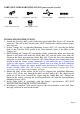
PARTS INCLUDED FOR INSTALLATION (parts are not to scale):
1
Ground Screw (#11) 2 outlet Box Screw (#7) 1 Crossbar (#10) 2 Mounting Screw (#12)
3 Wire Connectors (#9) 2 Knurled Knob (#2)
INSTALLATION INSTRUCTIONS:
1. Attach the Crossbar (#10) to the Outlet box using Outlet Box Screws (#7) from the
outlet box. The side of the Crossbar with “GND” marked on it and two convex points
must face out.
2. Secure Canopy (#1) by threading Mounting Screws (#12) 1/4” into the pre-drilled
holes in the Crossbar (#10) spaced at the same distances apart as the holes in the
Canopy (#1)
.
3. While holding the Canopy (#1) toward the ceiling, connect the white wire from the
fixture to the white wire from the Outlet Box (#8), and the black wire from the
fixture to the black wire from the Outlet Box (#8). Cover the two wire connections
using the two provided Wire Connectors (#9). Wrap the two wire connections with
electrical tape for a more secure connection. If your outlet box has a ground wire
(green or bare copper), connect fixture’s ground wire to it using the wire connector
(#9). Otherwise connect the copper ground from the fixture to Ground screw (#11)
on the Crossbar (#10). Note: If you have electrical questions, consult your local
electrical code for approved grounding methods.
4. Mount the body of the fixture on the wall by aligning the protruding Mounting
Screws (#12) all the way through the holes on the Canopy (#1). Be careful not to
pinch any of the wires between the fixture and the Outlet Box (#8). Tighten the
fixture to the wall by screwing the two Knurled Knobs (#2) onto the two protruding
Mounting Screws (#12).
5. Install Light bulbs in accordance with the fixture’s specifications. (DO NOT
EXCEED THE MAXIMUM WATTAGE RATING)
6. Installation is complete. Turn on the power at the circuit breaker or fuse box. Turn
the light switch on to activate the fixture.