Item #1002 706 090, 1002 707 960 Model #91350, 91359 UL Model #52-BVD ® USE AND CARE GUIDE CAMPBELL 52-INCH CEILING FAN Questions, problems, missing parts? Before returning to the store, call Hampton Bay Customer Service 8 a.m. - 6 p.m., EST, Monday-Friday 1-855-HD-HAMPTON HAMPTONBAY.COM To view an instructional video on how to install this product: 1. Go to www.homedepot.
Table of Contents Table of Contents................................................................. 2 Assembly............................................................................... 7 Safety Information................................................................ 2 Operation............................................................................ 15 Warranty................................................................................ 3 Care and Cleaning................................
Warranty The supplier warrants the fan motor to be free from defects in workmanship and material present at time of shipment from the factory for a lifetime after the date of purchase by the original purchaser. The supplier also warrants that all other fan parts, excluding any glass or acrylic blades, to be free from defects in workmanship and material at the time of shipment from the factory for a period of one year after the date of purchase by the original purchaser.
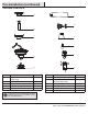
Pre-Installation (continued) HARDWARE INCLUDED NOTE: Hardware not shown to actual size.
Pre-Installation (continued) PACKAGE CONTENTS A F G B C H I J D K E Part A Description Quantity Slide-on mounting bracket (inside canopy) 1 B Ball/downrod assembly 1 C Canopy D E Part Description Quantity F Blade 5 G Blade bracket (with pre-installed screws) 5 1 H Glass shade 3 Fan-motor assembly 1 I LED bulbs (9 Watt maximum) 3 Light kit fitter assembly 1 J Remote control (battery included) 1 K Receiver 1 IMPORTANT: This product and/or components are governed
Installation MOUNTING OPTIONS NOTE: You may need a longer downrod to maintain proper blade clearance when installing on a steep, sloped ceiling. The maximum angle allowable is 20° away from horizontal. WARNING: To reduce the risk of fire, electric shock or personal injury, mount to an outlet box marked “Acceptable for fan support of 35 lbs. (15.9 kg) or less,” and use the screws provided with the outlet box.
Assembly - Standard Ceiling Mount 1 2 Preparing for standard mounting □□ Remove the canopy ring (L) from the canopy (C) by turning □□ □□ Routing the wires □□ Make sure the slot openings are on top and route the wires exiting the top of the fan-motor assembly (D) through the canopy (C) and the canopy ring (L) and then through the ball/downrod assembly (B). the ring counter-clockwise until it unlocks.
Assembly - Close-To-Ceiling Mount 1 2 Preparing for mounting □□ Remove canopy ring (L) from the canopy (C) by turning the ring □□ □□ □□ □□ Remove three of the six screws and lock washers (QQ) (every counter-clockwise until it unlocks. Remove the mounting bracket (A) from the canopy (C) by loosening the two canopy screws (JJ) located in the “L shaped” slots Remove and save the two canopy screws (II) in the round holes. This will enable you to remove the mounting bracket (A).
Assembly - Hanging the Fan (continued) 2 3 Hanging the fan WARNING: The hook (XX) is only to balance the fan while making the electrical connections. Failure to hang as shown may result in the hook (XX) breaking, causing the fan to fall. The hook must pass from the inside to the outside of the canopy. NOTE: The frequencies on your receiver and remote control have been preset at the factory.
Assembly - Hanging the Fan (continued) 4 5 Installing the receiver WARNING: To reduce the risk of fire or electric shock, remember to disconnect power. The electrical wiring must meet all local and national electrical code requirements. The electrical source and fan must be 110/120 volt, 60Hz. Do not use this product in conjunction with any variable wall control. Incorrect wire connection can damage this receiver.
Assembly - Hanging the Fan (continued) 6 Making the electrical connections Outlet box in the ceiling (MM) WARNING: Each wire connector supplied with this fan is designed to accept up to one 12-gauge house wire and two wires from the fan. If you have larger than 12-gauge house wiring or more than one house wire to connect to the fan wiring, consult an electrician for the proper size wire connectors to use.
Assembly - Hanging the Fan (continued) 7 8 Wrapping the extra wire Mounting the fan-motor assembly (standard mount) WARNING: When using the standard ball/downrod mounting, the tab in the ring at the bottom of the mounting bracket must rest in the groove of the hanger ball. Failure to properly seat the tab in the groove could cause damage to the wiring. NOTE: Follow this step ONLY if you did not cut the extra length off from the wires coming from the ceiling fan to the receiver.
Assembly - Hanging the Fan (continued) 9 Mounting the fan-motor assembly (close-to-ceiling mount) JJ A WARNING: The locking slots of the canopy are provided only as an aid to mounting. Do not leave the fan assembly unattended until all four canopy screws are engaged and firmly tightened. □□ Carefully unhook the fan from the slide-on mounting bracket □□ □□ □□ L C (A) and align the locking slots of the canopy (C) with the two screws in the slide-on mounting bracket (A).
Assembly - Attaching the lights 1 Attaching the light kit fitter assembly 2 Installing the glass shades and bulbs CAUTION: To reduce the risk of electric shock, disconnect the electrical supply circuit to the fan before installing the light fixture. WARNING: Allow the glass shades to cool completely before removing. NOTE: Notice the location of the fan’s slide switch. This is the switch used to change the fan’s directional rotation.
Operation OPERATING YOUR FAN Your fan is equipped with a remote control to operate the fan speed and lights of your new ceiling fan. The speed setting for warm or cool weather depends on factors such as the room size, ceiling height, number of fans and so on. The fan is shipped from the factory with the reversing switch positioned to circulate air downward.
Care and Cleaning WARNING: Make sure the power is off before cleaning your fan. □□ Because of the fan’s natural movement, some connections may become loose. Check the support connections, brackets, and blade attachments twice a year. Make sure they are secure. It is not necessary to remove the fan from the ceiling. □□ Clean your fan periodically to help maintain its new appearance over the years.
This equipment has been tested and found to comply with the limits for a Class B digital device, pursuant to Part 15 of the FCC Rules. These limits are designed to provide reasonable protection against harmful interference in a residential installation. This equipment generates, uses and can radiate radio frequency energy and, if not installed and used in accordance with the instructions, may cause harmful interference to radio communications.
® Artículo núm. 1002 706 090, 1002 707 960 Modelo núm. 91350, 91359 Modelo núm. 52-BVD aprobado por UL GUÍA DE USO Y MANTENIMIENTO VENTILADOR DE TECHO CAMPBELL, DE 1.32 M ¿Preguntas, problemas o piezas faltantes? Antes de regresar a la tienda, llama al Servicio al cliente de Hampton Bay de lunes a viernes, entre 8 a.m. y 6 p.m., (hora estándar del Este) 1-855-HD-HAMPTON HAMPTONBAY.COM Para ver un video instructivo sobre cómo instalar este producto: 1. Ir a www.homedepot.
Tabla de contenido Tabla de contenido ......................................................... 2 Ensamblaje...................................................................... 7 Información de seguridad .............................................. 2 Funcionamiento............................................................... 15 Garantía ........................................................................... 3 Mantenimiento y limpieza...............................................
Garantía El proveedor garantiza de por vida, a partir de la fecha en que el comprador original lo adquiere, que el motor del ventilador no presenta defectos de fabricación ni de materiales al momento en que es enviado desde la fábrica.
Preinstalación (continuación) HERRAJES INCLUIDOS NOTA: No se muestra el tamaño real de los herrajes.
Preinstalación (continuación) CONTENIDO DEL PAQUETE A F G B C H I J D K E Pieza A Descripción Cantidad Soporte deslizante de montaje (dentro de la cubierta) 1 B Ensamblaje de tubo bajante/bola 1 C Cubierta D E Pieza Descripción Cantidad F Aspa 5 G Soporte de aspa (con tornillos preinstalados) 5 1 H Pantalla de vidrio 3 Ensamblaje del motor del ventilador 1 I Bombillas LED (máximo de 9 W) 3 Ensamblaje del soporte del kit de luces 1 J Control remoto (batería incluida)
Instalación OPCIONES DE MONTAJE NOTA: Tal vez necesites un tubo bajante más largo para mantener la altura mínima adecuada de las aspas, al instalar el ventilador en un techo inclinado. El ángulo máximo permitido es de 20º de la posición horizontal. ADVERTENCIA: Para reducir el riesgo de incendio, descarga eléctrica u otras lesiones, instala sólo en una caja eléctrica clasificada como “apropiada para sostener ventiladores de 15.9 kg o menos”, y usa sólo los tornillos incluidos con la caja eléctrica.
Ensamblaje – Montaje estándar en techo 1 2 Preparación para montaje estándar □□ Retira el aro de cubierta (L) de la cubierta (C), girándolo en □□ □□ Disposición de los cables □□ Asegúrate de que las ranuras estén en la parte superior y pasa los cables existentes sobre la parte superior del ensamblaje del motor del ventilador (D) a través de la cubierta (C) y el aro de la cubierta (L) y luego a través del ensamblaje del tubo bajante/bola (B).
Ensamblaje – Montaje "cerca del techo" 1 2 Preparación para el montaje □□ Retira el anillo de cubierta (L) de la cubierta (C), girándolo en □□ □□ □□ Disposición de los cables □□ Retira tres de los seis tornillos y arandelas de seguridad (QQ) sentido contrario a las manecillas del reloj hasta soltarlo. Retira el soporte de montaje (A) de la cubierta (C) aflojando los dos tornillos de la cubierta (JJ) ubicados en las ranuras en forma de L.
Ensamblaje – Cómo colgar el ventilador 2 3 Cómo colgar el ventilador NOTA: Las frecuencias del receptor y el control remoto fueron preconfiguradas en la fábrica. Antes de instalar el receptor, asegúrate de que los interruptores en línea del receptor y el control remoto estén configurados en la misma frecuencia. Los interruptores en el control remoto están ubicados dentro del compartimento de la batería.
Ensamblaje – Cómo colgar el ventilador (continuación) 4 5 Cómo instalar el receptor ADVERTENCIA: Para reducir el riesgo de incendio o de descarga eléctrica, recuerda desconectar la electricidad. El cableado eléctrico debe cumplir todos los requisitos de códigos eléctricos nacionales y locales. La fuente de energía y el ventilador deben ser de 110/120 voltios y 60 Hz. No utilices este producto con ningún control de pared variable. Conectar el cableado de manera incorrecta dañará este receptor.
Ensamblaje – Cómo colgar el ventilador (continuación) 6 Cómo conectar los cables del ventilador a los del receptor Caja eléctrica en el techo (MM) ADVERTENCIA: Quita los tapones de goma del motor en la parte inferior del ventilador antes de instalar las aspas o de verificar el motor. Verde IMPORTANTE: Usa las tuercas de conexión de cables (AA) incluidas con el ventilador. Sujeta los conectores con cinta de electricista y asegúrate de que no haya conexiones o cables sueltos.
Ensamblaje - Cómo colgar el ventilador (continuación) 7 8 Cómo enroscar el cable sobrante Cómo montar el ventilador ADVERTENCIA: Cuando uses el montaje de tubo bajante y bola estándar, la pestaña en el aro en la parte inferior de la placa de montaje debe encajar en la ranura de la bola de soporte. Si la pestaña no se asienta correctamente en la ranura, se puede dañar el cableado. NOTA: Sigue estos pasos SOLAMENTE si no cortaste el cable sobrante del ventilador de techo hacia el receptor.
Ensamblaje – Cómo colgar el ventilador (continuación) 9 Cómo montar el ensamblaje del motor del ventilador (montaje "cerca del techo") ADVERTENCIA: Las ranuras de cierre de la cubierta sólo sirven de ayuda durante el montaje. No dejes sin supervisión el ensamblaje del ventilador hasta que los cuatro tornillos de la cubierta estén fijos y firmemente ajustados.
Ensamblaje - Cómo instalar las lámparas 1 Cómo instalar el ensamblaje del soporte del kit de luces 2 Cómo instalar las pantallas de vidrio y las bombillas PRECAUCIÓN: Para disminuir el riesgo de descarga eléctrica, desconecta el circuito de energía del ventilador antes de instalar la lámpara. ADVERTENCIA: Espera que la pantalla de vidrio se enfríe completamente antes de retirarla. NOTA: Marca la posición del interruptor deslizante del ventilador.
Funcionamiento CÓMO USAR EL VENTILADOR Tu ventilador está equipado con un control remoto que controla la velocidad y las luces de tu nuevo ventilador de techo. Las configuraciones de velocidad para clima cálido o frío dependen de factores como el tamaño de la habitación, la altura del techo, la cantidad de ventiladores y demás. Este ventilador se envía desde la fábrica con el interruptor de reversa posicionado para hacer circular el aire hacia abajo.
Mantenimiento y limpieza ADVERTENCIA: Asegúrate de que la corriente esté apagada antes de limpiar el ventilador. □□ Debido al movimiento natural del ventilador, algunas conexiones pueden aflojarse. Revisa las conexiones de soporte, soportes y accesorios de aspas dos veces al año. Verifica que estén seguros. No es necesario desmontar el ventilador del techo. □□ Limpia tu ventilador con frecuencia, para que luzca como nuevo con el paso de los años.
Este equipo ha sido probado y se determinó que cumple con los límites establecidos para un dispositivo digital Clase B, de acuerdo con la Parte 15 de las Normas de la FCC. Estos límites fueron establecidos para ofrecer protección razonable contra la interferencia dañina durante uso residencial. Este equipo genera, usa y puede irradiar energía de radiofrecuencia y, si no se instala y usa de acuerdo con las instrucciones, puede causar interferencia dañina a comunicaciones radiales.