Item #1002 706 090, 1002 707 960 Model #91350, 91359 UL Model #52-BVD USE AND CARE GUIDE CAMPBELL 52-INCH CEILING FAN Questions, problems, missing parts? Before returning to the store, call Hampton Bay Customer Service 8 a.m. - 6 p.m., EST, Monday-Friday 1-855-HD-HAMPTON HAMPTONBAY.COM To view an instructional video on how to install this product: 1. Go to www.homedepot.
Table of Contents Table of Contents................................................................. 2 Assembly............................................................................... 7 Safety Information................................................................ 2 Operation............................................................................ 14 Warranty................................................................................ 3 Care and Cleaning................................
Warranty The supplier warrants the fan motor to be free from defects in workmanship and material present at time of shipment from the factory for a lifetime after the date of purchase by the original purchaser. The supplier also warrants that all other fan parts, excluding any glass or acrylic blades, to be free from defects in workmanship and material at the time of shipment from the factory for a period of one year after the date of purchase by the original purchaser.
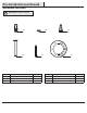
Pre-Installation (continued) HARDWARE INCLUDED NOTE: Hardware not shown to actual size.
Pre-Installation (continued) PACKAGE CONTENTS A F G B H C I J 1 2 3 4 ON DIP D K O E P Part A Description Quantity Slide-on mounting bracket (inside canopy) 1 B Ball/downrod assembly 1 C Canopy D E Part Description Quantity F Blade 5 G Blade bracket (with pre-installed screws) 5 1 H Glass shade 3 Fan-motor assembly 1 I LED bulbs (9.
Installation MOUNTING OPTIONS NOTE: You may need a longer downrod to maintain proper blade clearance when installing on a steep, sloped ceiling. The maximum angle allowable is 20° away from horizontal. WARNING: To reduce the risk of fire, electric shock or personal injury, mount to an outlet box marked “Acceptable for fan support of 35 lbs. (15.9 kg) or less,” and use the screws provided with the outlet box.
Assembly - Standard Ceiling Mount 1 2 Preparing for standard mounting □ Remove the canopy ring (L) from the canopy (C) by turning □ □ □ the ring counter-clockwise until it unlocks. Remove the mounting bracket (A) from the canopy (C) by loosening the two canopy screws (JJ) located in the “L shaped” slots. Remove and save the two canopy screws (II) in the round holes. This will enable you to remove the mounting bracket (A).
Assembly - Close-To-Ceiling Mount 1 2 Preparing for mounting □ Remove canopy ring (L) from the canopy (C) by turning the ring □ □ □ □ Remove three of the six screws and lock washers (QQ) (every counter-clockwise until it unlocks. Remove the mounting bracket (A) from the canopy (C) by loosening the two canopy screws (JJ) located in the “L shaped” slots Remove and save the two canopy screws (II) in the round holes. This will enable you to remove the mounting bracket (A).
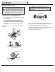
Assembly - Hanging the Fan (continued) 2 3 Hanging the fan WARNING: The hook (XX) is only to balance the fan while making the electrical connections. Failure to hang as shown may result in the hook (XX) breaking, causing the fan to fall. The hook must pass from the inside to the outside of the canopy. NOTE: The frequencies on your receiver and remote control have been preset at the factory.
Assembly - Hanging the Fan (continued) 4 5 Installing the receiver WARNING: To reduce the risk of fire or electric shock, remember to disconnect power. The electrical wiring must meet all local and national electrical code requirements. The electrical source and fan must be 110/120 volt, 60Hz. Do not use this product in conjunction with any variable wall control. Incorrect wire connection can damage this receiver.
Assembly - Hanging the Fan (continued) 6 7 Making the electrical connections NOTE: The fan comes with 12 in. lead wires for use with the provided 4.5 in. ball downrod assembly (B), if you wish to use longer downrod, you can use the extension lead wire (42 in.) (O) provided. WARNING: When using the standard ball/downrod mounting, the tab in the ring at the bottom of the mounting bracket must rest in the groove of the hanger ball.
Assembly - Hanging the Fan (continued) 8 Mounting the fan-motor assembly (close-to-ceiling mount) JJ A WARNING: The locking slots of ceiling canopy are provided only as an aid to mounting. Do not leave the fan assembly unattended until all four canopy screws are engaged and firmly tightened. □ Carefully unhook the fan from the mounting bracket (A) and □ □ □ L align the locking slots of the ceiling canopy (C) with the two screws in the mounting bracket (A).
Assembly - Attaching the lights 1 Attaching the light kit fitter assembly 2 CAUTION: To reduce the risk of electric shock, disconnect the electrical supply circuit to the fan before installing the light fixture. WARNING: Allow the glass shades to cool completely before removing. NOTE: Notice the location of the fan’s slide switch. This is the switch used to change the fan’s directional rotation. For more information on the operation of this switch, see Operating Your Fan and Remote Control on page 14.
Operation OPERATING YOUR FAN Your fan is equipped with a remote control to operate the fan speed and lights of your new ceiling fan. The speed setting for warm or cool weather depends on factors such as the room size, ceiling height, number of fans and so on. The fan is shipped from the factory with the reversing switch positioned to circulate air downward.
Assembly - Attaching the Accessories Mounting the remote control holder Screw cover plate NOTE: Screw wall anchors are included for extra support. The included screws are designed to screw easily into the wall. If you would like a more permanent or secure hold, install the wall anchors prior to attaching the wall cradle to the wall. □ Slide the screw cover plate up to remove it from the wall □ □ cradle.
Care and Cleaning WARNING: Make sure the power is off before cleaning your fan. □ Because of the fan’s natural movement, some connections may become loose. Check the support connections, brackets, and blade attachments twice a year. Make sure they are secure. It is not necessary to remove the fan from the ceiling. □ Clean your fan periodically to help maintain its new appearance over the years.
This equipment has been tested and found to comply with the limits for a Class B digital device, pursuant to Part 15 of the FCC Rules. These limits are designed to provide reasonable protection against harmful interference in a residential installation. This equipment generates, uses and can radiate radio frequency energy and, if not installed and used in accordance with the instructions, may cause harmful interference to radio communications.