
Instructions / Assembly


8
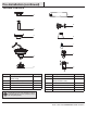
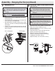
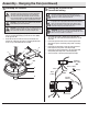
□ Remove three of the six screws and lock washers (QQ) (every
other one) securing the motor collar (N) to the top of the fan-
motor assembly (D).
□ Place the rubber gasket (FF) over the remaining three screws,
route the wires exiting the top of the fan-motor assembly (D)
through the canopy (C) and canopy ring (L) (make sure the slot
openings are on top), and then place the canopy (C) over the
collar at the top of the fan-motor assembly (D).
□ Align the mounting holes with the holes in the motor and
fasten using the three screws and lock-washers (QQ) removed
previously. Tighten the mounting screws securely.
C
FF
D
QQ
N
L
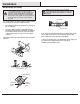
Attaching the fan to the electrical
box
□ Pass the 120-Volt supply wires through the center hole in the
slide-on mounting bracket (A).
□ Install the slide-on mounting bracket (A) on the outlet box by
sliding the slide-on mounting bracket (A) over the two screws (TT)
provided with the outlet box. If necessary, use leveling washers
(not included) between the slide-on mounting bracket (A) and
the outlet box. The at side of the slide-on mounting bracket (A)
should face toward the outlet box, as shown.
□ Securely tighten the two mounting screws (TT).
1
WARNING: To reduce the risk of re, electric shock
or personal injury, mount to an outlet box marked
“Acceptable for fan support of 35 lbs. (15.9 kg) or less,”
and use the screws provided with the outlet box.
A
TT
TT
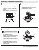
Routing the wiresPreparing for mounting
21
□ Remove canopy ring (L) from the canopy (C) by turning the ring
counter-clockwise until it unlocks.
□ Remove the mounting bracket (A) from the canopy (C) by
loosening the two canopy screws (JJ) located in the “L
shaped” slots
□ Remove and save the two canopy screws (II) in the round
holes. This will enable you to remove the mounting bracket (A).
□ Remove the decorative canopy bottom cover (M) from the
canopy (C) by pressing the three studs located inside the
bottom of the canopy.
M
A
C
II
L
JJ
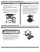
Assembly - Close-To-Ceiling Mount
Assembly - Hanging the Fan