
Use and Care Guide

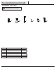

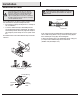
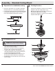
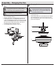
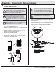
Table Of Contents

9
HAMPTONBAY.COM
Please contact 1-855-HD-HAMPTON for further assistance.
Assembly - Hanging the Fan (continued)
4
Installing the receiver
□ Position the house supply wires (AAA) to one side of the
slide-on mounting bracket (A); position the fan wires (BBB)
to the opposite side.
□ Insert the narrow end of the receiver (L) (as shown, at side
towards the ceiling) into the slide-on mounting bracket (A)
until it rests on top of the ball/downrod assembly (D).
WARNING: To reduce the risk of re or electric shock,
remember to disconnect power. The electrical wiring must
meet all local and national electrical code requirements.
The electrical source and fan must be 110/120 volt, 60Hz.
Do not use this product in conjunction with any variable wall
control. Incorrect wire connection can damage this receiver.
CAUTION: Do not immerse in water. Do not pull on or cut the
receiver leads shorter. Do not drop or bump the unit.
BBB
A
L
D
AAA
L
B
C
Setting the code on the remote
control and receiver
3
NOTE: The frequencies on your receiver and hand unit have
been preset at the factory. Before installing the receiver,
make sure the dip switches on the receiver and hand unit
are set to the same frequency. The dip switches on the hand
unit are located inside the battery compartment.
NOTE: The switch marked “O/D” controls the dimming
function of the lights. If you are using non-dimmable bulbs,
use a ballpoint pen or small screwdriver to set the switch
to “O” to disable the dimming function. If you are using
dimmable bulbs, set the switch to “D” to enable the dimming
function.
NOTE: The battery will weaken with age and should be
replaced before leaking takes place, as battery leakage
damages the hand unit. Dispose of the used battery properly
and keep the battery out of the reach of children.
□ Remove the remote control (K) battery cover by pressing rmly
on the arrow and sliding the cover off.
□ Slide the dip switches (ZZ) to your choice of either up or down.
The factory setting is up.
□ Slide the dip switches (ZZ) on the receiver (L) to the same
position as set on the remote control (K).
□ Install the 23A 12V battery (included).
□ Replace the battery cover on the remote control (K).
□ Insert the silicone rubber stopper (OO) into the hole on the
receiver (L) to cover the dip switches.
K
L
ZZ
1 2 3 4
ON
OO
1 2
3
4
ON 0
1 2
3
4
ON
D
D
0