® Item # 795-838, 795-871, 795-904, 850-919, 850-193 Model #51012, 51013, 51014, 51090, 51091 UL model # 52-CCT USE AND CARE GUIDE LYNDHURST 52-INCH CEILING FAN Questions, problems, missing parts? Before returning to the store, call Hampton Bay Customer Service 8 a.m. - 7 p.m., EST, Monday-Friday, 9 a.m. - 6 p.m., EST Saturday 1-855-HD-HAMPTON HAMPTONBAY.COM To view an instructional video on how to install this product: 1. Go to www.homedepot.
Table of Contents Table of Contents................................................................. 2 Assembly............................................................................... 7 Safety Information................................................................ 2 Operation............................................................................ 12 Warranty................................................................................ 3 Care and Cleaning................................
Warranty The supplier warrants the fan motor to be free from defects in workmanship and material present at time of shipment from the factory for a lifetime after the date of purchase by the original purchaser. The supplier also warrants that all other fan parts, excluding any glass or acrylic blades, to be free from defects in workmanship and material at the time of shipment from the factory for a period of one year after the date of purchase by the original purchaser.
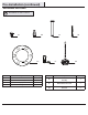
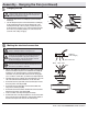
Pre-Installation (continued) HARDWARE INCLUDED NOTE: Hardware not shown to actual size.
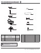
Pre-Installation (continued) PACKAGE CONTENTS A F B G C H D I E J Part Description Quantity A Slide-on mounting bracket (inside canopy) 1 B Ball/downrod assembly C D Part Description Quantity E Light kit fitter assembly 1 F Decorative motor collar cover 1 1 G Blade 5 Canopy with canopy ring attached 1 H Blade bracket 5 Fan-motor assembly 1 I Glass shade 4 J LED bulb, 9.
Installation MOUNTING OPTIONS WARNING: To reduce the risk of fire, electric shock or personal injury, mount to outlet box marked “Acceptable for fan support of 35lbs. (15.9kg) or less”, and use screws provided with the outlet box. An outlet box commonly used for the support of lighting fixtures may not be acceptable for fan support and may need to be replaced. If in doubt, consult a qualified electrician.
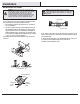
Assembly - Standard Ceiling Mount 1 2 Preparing for mounting □□ Remove the canopy ring (K) from the canopy (C) by □□ □□ Routing the wires □□ Route the wires exiting the top of the fan motor (D) into the decorative motor collar cover (F) and through the canopy ring (K). turning the ring counterclockwise until it unlocks. Remove the mounting bracket (A) from the canopy (C) by loosening the two canopy screws (II) located in the “L” shaped slots.
Assembly - Close-To-Ceiling Mount 1 2 Close-to-Ceiling Mounting □□ Remove the canopy ring (K) from the canopy (C) by turning □□ □□ □□ Routing the wires □□ Remove three of the six screws and lock washers (every other the ring counterclockwise until it unlocks. Remove the mounting bracket (A) from the canopy (C) by loosening the two canopy screws (II) located in the “L” shaped slots. Remove and save the two canopy screws (JJ) in the round holes. This will enable you to remove the mounting bracket (A).
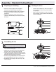
Assembly - Hanging the Fan (continued) 5 Hanging the fan WARNING: The hook as shown is only to balance the fan while attaching wiring. Failure to hang as shown may result in hook breaking, causing the fan to fall. The hook must pass from inside to the outside of the canopy. A A B □□ Carefully lift the fan motor assembly (D) up to the mounting bracket (A). C D □□ Seat the hanger ball portion of the ball/downrod assembly (B) in the mounting bracket socket.
Assembly - Hanging the Fan (continued) 7 Wrapping the extra wire NOTE: Follow this step ONLY if you did not cut the extra length from the wires coming from the ceiling fan. □□ Gently wrap the excess wire around the mounting bracket. □□ Secure the wires with electrical tape. 8 Mounting the fan Close-to-Ceiling mounting WARNING: The locking slots of ceiling canopy are provided only as an aid to mounting.
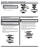
Assembly - Attaching the Fan Blades 9 Attaching the fan blades NOTE: Your fan blades are reversible. Select the blade side finish which best accentuates you decor. AA □□ Attach a blade (G) to a blade bracket (H) using the screws □□ □□ □□ (AA) provided. Please note that the rubber washers are pre-attached to the blade bracket (H). Insert a screw into the blade bracket (H). Repeat for the two remaining screws (AA). Tighten each screw securely.
Operation Turn on the power and check the operation of the fan. The pull chain controls the fan speeds as follows: 1 pull - High, 2 pulls - Medium, 3 pulls - Low, 4 pulls - off The appropriate speed settings for warm or cool weather depends on factors such as the room size, ceiling height, and number of fans. The slide switch controls the direction of the blades: forward (switch left) or reverse (switch right) NOTE: Wait for the fan to stop before reversing the direction of blade rotation.
Care and Cleaning WARNING: Make sure the power is off before cleaning your fan. □□ Because of the fan’s natural movement, some connections may become loose. Check the support connections, brackets, and blade attachments twice a year. Make sure they are secure. It is not necessary to remove the fan from the ceiling. □□ Clean your fan periodically to help maintain its new appearance over the years.
® Questions, problems, missing parts? Before returning to the store, call Hampton Bay Customer Service 8 a.m. - 7 p.m., EST, Monday-Friday, 9 a.m. - 6 p.m., EST, Saturday 1-855-HD-HAMPTON HAMPTONBAY.COM Retain this manual for future use.
® Artículo # 795-838, 795-871, 795-904, 850-919, 850-193 Modelo # 51012, 51013, 51014, 51090, 51091 Modelo # 52-CCT Aprobado por UL GUÍA DE USO Y MANTENIMIENTO VENTILADOR DE TECHO LYNDHURST DE 1.3 M ¿Preguntas, problemas o piezas faltantes? Antes de devolver a la tienda, llama al servicio al cliente de Hampton Bay, de 8:00 a.m. a 7:00 p.m. (Este), de lunes a viernes, y los sábados de 9:00 a.m. a 6:00 p.m. (Este). 1-855-HD-HAMPTON HAMPTONBAY.
Tabla de contenido Tabla de contenido............................................................... 2 Ensamblaje............................................................................ 7 Información de seguridad................................................... 2 Funcionamiento.................................................................. 12 Garantía................................................................................. 3 Mantenimiento y limpieza.....................................
Garantía El proveedor garantiza de por vida, a partir de la fecha de adquisición por el comprador original, que el motor del ventilador no presenta defectos de fabricación ni de materiales al momento del envío desde la fábrica. El proveedor también garantiza, por un año a partir de la fecha de adquisición por el comprador original, que ninguna de las demás piezas del ventilador, sin incluir las aspas de vidrio o acrílico, presenta defectos de fabricación o de material al momento del envío desde la fábrica.
Preinstalación (continuación) HERRAJES INCLUIDOS NOTA: Los herrajes no se muestran en tamaño real.
Preinstalación (continuación) CONTENIDO DEL PAQUETE A F B G C H D I E J Pieza Descripción Cantidad A Soporte de montaje deslizante (dentro de la cubierta) 1 B Conjunto de tubo bajante/bola C D Pieza Descripción Cantidad E Ensamblaje del soporte del kit de luces 1 F Cubierta decorativa del collarín del motor 1 1 G Aspa 5 Cubierta con anillo de cubierta incorporado 1 H Soporte de aspa 5 Conjunto motor-ventilador 1 I Pantalla de vidrio 4 J Bombilla LED, 9.5 W Máx.
Instalación OPCIONES DE MONTAJE ADVERTENCIA: Para reducir el riesgo de incendio, descarga eléctrica o lesiones personales, instala sólo en una caja eléctrica clasificada como “apropiada para sostener ventiladores de 15.9 kg o menos”, y usa sólo los tornillos incluidos con dicha caja. Las cajas eléctricas utilizadas comúnmente para el soporte de lámparas pudieran no servir como soporte de ventilador y tal vez deban reemplazarse. En caso de duda, consulta a un electricista calificado.
Ensamblaje - Montaje estándar en el cielo raso 1 2 Preparación para el montaje □□ Retira el aro (K) de la cubierta (C) girándolo hacia la □□ □□ Disposición de los cables □□ Inserta los cables que salen por la parte superior del motor del ventilador (D) en la cubierta decorativa del collarín del motor (F) y a través del aro de la cubierta (K).
Ensamblaje – Montaje cerca del cielo raso 1 2 Montaje cerca del techo □□ Retira el aro (K) de la cubierta (C) girándolo hacia la □□ □□ □□ Disposición de los cables □□ Retira tres de los seis tornillos y arandelas de seguridad izquierda hasta que se libere. Retira el soporte de montaje (A) de la cubierta (C) aflojando los dos tornillos de la cubierta (II) ubicados en las ranuras en forma de “L”. Quita y guarda los dos tornillos de la cubierta (JJ) en los orificios redondos.
Ensamblaje - Cómo colgar el ventilador (continuación) 5 Cómo colgar el ventilador ADVERTENCIA: El gancho, tal y como se muestra, es solo para sostener el ventilador mientras se conectan los cables. Si no se cuelga como se muestra puede romperse el gancho, y el ventilador se caerá. El gancho tiene que pasar desde adentro hacia fuera de la cubierta. A B □□ Levanta con cuidado el conjunto motor-ventilador (D) hasta el □□ 6 A C D soporte de montaje (A).
Ensamblaje - Cómo colgar el ventilador (continuación) 7 Cómo enroscar el cable sobrante NOTA: Sigue estos pasos SÓLO si no cortaste el cable sobrante del ventilador de techo. □□ Con cuidado, enrolla el exceso de cable alrededor del soporte de montaje. □□ Asegura los cables con cinta de electricista. 8 Cómo montar el ventilador Montaje cerca del techo ADVERTENCIA: Las ranuras de cierre de la cubierta del techo sólo sirven de ayuda durante la instalación.
Ensamblaje - Cómo fijar las aspas del ventilador 9 Cómo fijar las aspas del ventilador NOTA: Las aspas de tu ventilador son reversibles. Elige el acabado del aspa por el lado que mejor resalte tu decoración. AA □□ Fija un aspa (G) a su soporte (H) con los tornillos (AA) □□ □□ □□ provistos. Observa que las arandelas de goma están fijadas en el soporte del aspa (H). Inserta el tornillo en el soporte del aspa (H). Repite para los otros dos tornillos (AA) restantes.
Funcionamiento Enciende la electricidad y verifica el funcionamiento del ventilador. El interruptor de cadena controla las velocidades del ventilador de la siguiente manera: 1 vez: alta, 2 veces: media, 3 veces: baja y 4 veces: apagado Las configuraciones de velocidad apropiadas para clima cálido o frío dependen de factores como el tamaño de la habitación, la altura del techo y la cantidad de ventiladores.
Mantenimiento y limpieza ADVERTENCIA: Asegúrate de que la electricidad esté apagada antes de limpiar el ventilador. □□ Debido al movimiento natural del ventilador, algunas conexiones pueden aflojarse. Revisa dos veces al año las conexiones de soporte, los soportes y los accesorios de las aspas. Comprueba que estén seguros. No es necesario desmontar el ventilador del techo. □□ Limpia el ventilador con frecuencia para que luzca como nuevo al paso de los años. No uses agua al limpiar.
® ¿Preguntas, problemas o piezas faltantes? Antes de devolver a la tienda, llama al servicio al cliente de Hampton Bay, de 8:00 a.m. a 7:00 p.m. (Este), de lunes a viernes, y los sábados de 9:00 a.m. a 6:00 p.m. (Este). 1-855-HD-HAMPTON HAMPTONBAY.COM Conserva este manual para uso futuro.