Item #XXX-XXX Model #91171 UL Model #52-WK USE AND CARE GUIDE PALISADES 52-INCH CEILING FAN Questions, problems, missing parts? Before returning to the store, call Hampton Bay Customer Service 8 a.m. - 6 p.m., EST, Monday-Friday. 1-855-HD-HAMPTON HAMPTONBAY.COM To view an instructional video on how to install this product: 1. Go to www.homedepot.com and enter either the Item or Model number, found in the top right corner of the cover of this instruction manual, in the search field. 2.
Table of Contents Table of Contents................................................................. 2 Assembly............................................................................... 7 Safety Information................................................................ 2 Operation............................................................................ 13 Warranty................................................................................ 3 Care and Cleaning................................
Warranty The supplier warrants the fan motor to be free from defects in workmanship and material present at time of shipment from the factory for a lifetime after the date of purchase by the original purchaser. The supplier also warrants that all other fan parts, excluding any glass or acrylic blades, to be free from defects in workmanship and material at the time of shipment from the factory for a period of one year after the date of purchase by the original purchaser.
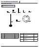
Pre-Installation (continued) HARDWARE INCLUDED NOTE: Hardware not shown to actual size.
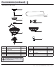
Pre-Installation (continued) PACKAGE CONTENTS A B G C H F I D J E Part Description Quantity A Slide-on mounting bracket (inside canopy) 1 B Ball/downrod assembly 1 C Canopy with canopy ring attached 1 D Fan-motor assembly E Light kit fitter assembly Part Description Quantity F Decorative motor collar cover 1 G Blade 5 H Blade bracket (flange), screws (pre-installed) 5 1 I Glass bowl 1 1 J LED Light bulb, 9.
Installation MOUNTING OPTIONS NOTE: You may need a longer downrod to maintain proper blade clearance when installing on a steep, sloped ceiling. The maximum angle allowable is 30° away from horizontal. WARNING: To reduce the risk of fire, electric shock or personal injury, mount to outlet box marked “acceptable for fan support of 35lbs. (15.9 Kg) or less” and use screws provided with the outlet box.
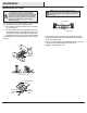
Assembly - Standard Ceiling Mount 1 2 Preparing for standard mounting Routing the wires □□ Remove the canopy ring (KK) from the canopy (C) by □□ □□ □□ Route the wires exiting the top of the fan motor (D) into the decorative motor collar cover (F) and through the canopy ring (KK). turning the ring counter clockwise until it unlocks.
Assembly - Close-To-Ceiling Mount 1 2 Preparing for close-to-ceiling mounting Routing the wires □□ Remove the canopy ring (KK) from the canopy (C) by □□ Remove three of the six screws and lockwashers (MM) (every □□ □□ turning the ring counter clockwise until it unlocks. Remove the mounting bracket (A) from the canopy (C) by loosening the two canopy screws (II) located in the “L shaped slots”. Remove and save the two canopy screws (JJ) in the round holes.
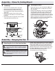
Assembly - Hanging the Fan (continued) 5 Hanging the fan WARNING: The hook is only to hold the fan while attaching wiring. Failure to hang the fan properly by following these instructions may result in the hook breaking, causing the fan to fall. The hook must pass from inside to the outside of the canopy. A B C A C □□ Carefully lift the fan motor assembly (D) up to the mounting bracket (A). D D □□ Seat the hanger ball portion of the ball/downrod assembly (B) in the mounting bracket socket.
Assembly - Hanging the Fan (continued) 7 Wrapping the extra wire NOTE: Follow this step ONLY if you did not cut the extra length off from the wires coming from the ceiling fan. □□ Gently wrap the excess wire around the mounting bracket. □□ Secure with electrical tape. 8 Mounting the fan - standard Mounting the fan close-to-ceiling WARNING: The locking slots of the ceiling canopy are provided only as an aid to mounting.
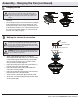
Assembly - Attaching the Fan Blades 9 Attaching the fan blades □□ Attach blade (G) to blade bracket (H) using the screws (AA) □□ □□ AA provided. Please note that the rubber washers are preattached to the blade bracket (H). Insert a screw into the blade bracket (H). Repeat for the two remaining screws (AA). Tighten each screw securely. Repeat these steps for the remaining blades.
Assembly - Attaching the Light Kit 11 12 Attaching the light kit fitter assembly WARNING: To reduce the risk of electric shock, disconnect the electrical supply circuit to the fan before installing the light fixture. Installing the glass shades and bulbs CAUTION: Make sure the fan switch chain does not make contact with the light bulbs. □□ Loosen the three screws on the switch cup cover of the □□ Remove the bottom cover and the finial from the light kit □□ □□ □□ light kit fitter assembly (E).
Assembly - Assembling The Fan Without The Light Kit 13 Assembling the fan without the light □□ In order to use the fan without the light kit, remove switch □□ □□ □□ cup cover from the top of the light kit fitter assembly (E) by removing center hex nut inside switch cup cover, and then thread switch cup cover off of the threaded nipple on the top of the light kit fitter assembly (E). Remove three screws. Press plastic plug (EE) into the center hole of the switch cup cover.
Care and Cleaning WARNING: Make sure the power is off before cleaning your fan. □□ Because of the fan’s natural movement, some connections may become loose. Check the support connections, brackets, and blade attachments twice a year. Make sure they are secure. It is not necessary to remove the fan from the ceiling. □□ Clean your fan periodically to help maintain its new appearance over the years.
Questions, problems, missing parts? Before returning to the store, call Hampton Bay Customer Service 8 a.m. - 6 p.m., EST, Monday-Friday 1-855-HD-HAMPTON HAMPTONBAY.COM Retain this manual for future use.
Artículo Núm. XXX-XXX Modelo Núm. 91171 Modelo Núm. 52-WK Aprobado por UL GUÍA DE USO Y CUIDADO DEL PRODUCTO VENTILADOR DE TECHO PALISADES DE 1,32M ¿Preguntas, problemas o piezas faltantes? Antes de volver a la tienda, llama al Servicio al Cliente de Hampton Bay de lunes a viernes de 8 a.m. a 6 p.m., Hora Estándar del Este 1-855-HD-HAMPTON HAMPTONBAY.COM Para ver un video instructivo sobre cómo instalar este producto: 1. Ir a www.homedepot.
Índice Índice..................................................................................... 2 Ensamblaje ........................................................................... 7 Información de Seguridad................................................... 2 Operación............................................................................ 13 Garantía................................................................................. 3 Cuidado y Mantenimiento...................................
Garantía El proveedor garantiza de por vida, a partir de la fecha de compra por el comprador original, que el motor del ventilador no presenta defectos de fabricación ni de material desde la fecha de salida de la fábrica.
Pre-Instalación (continuación) INCLUYE HERRAJES NOTA: Los herrajes no se muestran en tamaño real.
Pre-Instalación (continuación) CONTENIDOS DEL PAQUETE A B G C H F I D J E Pieza Descripción Cantidad Pieza Descripción Cantidad A Soporte de montaje deslizante (dentro de la cubierta) 1 F Cubierta decorativa del collarín del motor 1 B Ensamblaje de tubo bajante/bola 1 G Aspa 5 C Cubierta con anillo de cubierta acoplado 1 H Brazos del aspa (reborde), tornillos (pre-instalados) 5 D Ensamblaje del motor del ventilador 1 I Tazón de vidrio 1 E Ensamblaje del soporte del j
Instalación OPCIONES DE MONTAJE ADVERTENCIA: Para reducir el riesgo de incendio, descarga eléctrica o lesiones personales, monta el ventilador sobre una caja eléctrica marcada como “aprobada como soporte de ventiladores de 35 lb (15,9 kg) o menos”, y usa los tornillos de montaje que vienen con la caja eléctrica. Es posible que una caja eléctrica comúnmente usada para el soporte de lámparas no sea aceptable para el soporte de ventilador y necesita remplazarse.
Ensamblaje – Montaje de Techo Estándar 1 2 Preparación para el montaje Insertar los cables □□ Retira el aro de cubierta (KK) de la cubierta (C), girándolo en □□ □□ □□ Inserta los cables que salen por la parte superior sentido contrario a las manecillas del reloj hasta soltarlo. Retira el soporte de montaje (A) de la cubierta (C) aflojando los dos tornillos de la cubierta (II) ubicados en las ranuras en forma de L. Quita y guarda los dos tornillos de la cubierta (JJ) en los orificios redondos.
Ensamblaje – Montaje "Cerca del Techo" 1 ☐☐ ☐☐ ☐☐ ☐☐ 2 Preparación de montaje cerca del techo Retira el aro de cubierta (KK) de la cubierta (C), girándolo en sentido contrario a las manecillas del reloj hasta soltarlo. Retira el soporte de montaje (A) de la cubierta (C) aflojando los dos tornillos de la cubierta (II) ubicados en las ranuras en forma de L. Quita y guarda los dos tornillos de la cubierta (JJ) en los orificios redondos. Esto te permitirá retirar el soporte de montaje (A).
Ensamblaje – Cómo Colgar el Ventilador (continuación) 5 Cómo colgar el ventilador A ADVERTENCIA: El gancho sólo es para sostener el ventilador mientras se conectan los cables. Si no se cuelga el ventilador correctamente siguiendo estas instrucciones, puede romperse el gancho, y el ventilador caerse. El gancho debe pasar de adentro hacia fuera de la cubierta. ☐☐ ☐☐ 6 B C A C D D Levanta con cuidado el ensamblaje del motor del ventilador (D) hasta el soporte de montaje (A).
Ensamblaje – Cómo Colgar el Ventilador (continuación) 7 Cómo enrollar el cable sobrante NOTA: Sigue estos pasos SOLAMENTE si no cortaste el cable sobrante del ventilador de techo. □□ Con cuidado, enrolla el exceso de cable alrededor del soporte de montaje. □□ Asegura con cinta de electricista.
Ensamblaje – Cómo Unir las Aspas del Ventilador 9 ☐☐ ☐☐ ☐☐ Cómo unir las aspas del ventilador AA Une un aspa (G) a un soporte de aspa (H) insertando los tornillos (AA) en los orificios del aspa y a través del soporte del aspa. Observa que las arandelas de goma están fijadas en el soporte del aspa. Aprieta todos los tornillos de manera firme. Repite estos pasos con cada aspa (G) y soporte de aspa (H).
Ensamblaje – Cómo Instalar el Kit de Luces 11 12 Cómo instalar el ensamblaje del soporte del kit de luces ADVERTENCIA: Para disminuir el riesgo de descarga eléctrica, desconecta el circuito de energía del ventilador antes de instalar la lámpara. ☐☐ ☐☐ ☐☐ Cómo instalar el tazón de vidrio y las bombillas PRECAUCIÓN: Asegúrate de que la cadena del interruptor no esté en contacto con las bombillas de luz.
Ensamblaje – Cómo Ensamblar el Ventilador Sin el Kit de Luces 13 Cómo ensamblar el ventilador sin la luz □□ Con el fin de utilizar el ventilador sin el kit de luces, retira □□ □□ □□ la cubierta de la caja del interruptor ubicado en la parte superior del ensamblaje del soporte del kit de luces (E), retirando la tuerca hexagonal del centro dentro de la cubierta de la caja del interruptor; y luego, desenrosca la cubierta de la caja del interruptor de la boquilla enroscada sobre el ensamblaje del soporte
Mantenimiento y Limpieza ADVERTENCIA: Asegúrate de que la corriente esté apagada antes de limpiar el ventilador. ☐☐ ☐☐ ☐☐ ☐☐ Debido al movimiento natural del ventilador, algunas conexiones pueden aflojarse. Revisa las conexiones de soporte, soportes y accesorios de aspas dos veces al año. Verifica que estén seguros. No es necesario desmontar el ventilador del techo. Limpia tu ventilador con frecuencia, para que luzca como nuevo con el paso de los años.
¿Preguntas, problemas o piezas faltantes? Antes de volver a la tienda, llama al Servicio al Cliente de Hampton Bay de lunes a viernes de 8 a.m. a 6 p.m., Hora Estándar del Este 1-855-HD-HAMPTON HAMPTONBAY.COM Guarda este manual para uso futuro.