Item #142-303 Model #51332 UL Model #52-MNL USE AND CARE GUIDE HAYWARD 52-INCH CEILING FAN Questions, problems, missing parts? Before returning to the store, call Hampton Bay Customer Service 8 a.m. - 6 p.m., EST, Monday-Friday. 1-877-527-0313 HAMPTONBAY.COM THANK YOU We appreciate the trust and confidence you have placed in Hampton Bay through the purchase of this ceiling fan. We strive to continually create quality products designed to enhance your home.
Table of Contents Table of Contents................................................................. 2 Assembly............................................................................... 7 Safety Information................................................................ 2 Operation............................................................................ 10 Warranty................................................................................ 3 Care and Cleaning................................
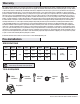
Warranty The supplier warrants the fan motor to be free from defects in workmanship and material present at time of shipment from the factory for a lifetime after the date of purchase by the original purchaser. The supplier also warrants that all other fan parts, excluding any glass or acrylic blades, to be free from defects in workmanship and material at the time of shipment from the factory for a period of one year after the date of purchase by the original purchaser.
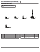
Pre-Installation (continued) hardwarE included NOTE: Hardware not shown to actual size.
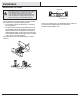
Pre-Installation (continued) package contents A E B F C G H D Part Description Quantity Part Description Quantity A Mounting plate 1 E Blade 5 B Motor housing 1 F Light kit fitter assembly 1 C Fan-motor assembly 1 G Glass shade 4 D Blade bracket (flange), screws pre-installed 5 H Light bulbs, 40-Watt maximum 4 IMPORTANT: This product and/or components are governed by one or more of the following U.S.
Installation Mounting Options Hanger Bar WARNING: To reduce the risk of fire, electric shock or personal injury, mount to outlet box marked “Acceptable for fan support of 35 lbs. (15.9 kg) or less”, and use screws provided with the outlet box. An outlet box commonly used for the support of lighting fixtures may not be acceptable for fan support and may need to be replaced. If in doubt, consult a qualified electrician.
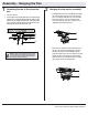
Assembly - Hanging the Fan 1 2 Attaching the fan to the electrical box Hanging the fan-motor assembly □□ Carefully lift the fan-motor assembly (C) and engage the slot in the motor bracket on the top of the fanmotor assembly (C) with the hook on the mounting plate (A) so that it is securely suspended. Then connect the wiring to your fan according to step 3 “Making the Electrical Connections”. □□ Turn the power off.
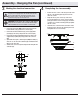
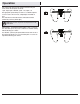
3 4 Making the electrical connection IMPORTANT: Use the plastic wire connectors (CC) supplied with your fan. Secure the connectors with electrical tape and ensure there are no loose strands or connections. □□ Connect the green wire (MM) from the motor bracket to the □□ □□ □□ household wire using a plastic wire connector (CC). Connect the fan motor white wire (LL) to the supply white (neutral) (LL) wire using a the plastic wire connector (CC).
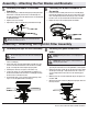
Assembly - Attaching the Fan Blades and Brackets 5 6 Attaching the blades to the blade brackets Fastening the blade assemblies to the motor □□ Attach a blade (E) to a blade bracket (D) by inserting the blade □□ Fasten the blade assembly to the fan-motor assembly (C) by □□ □□ □□ attachment screws (AA) into the holes in the blade (E) and through the blade bracket. The rubber washers are preattached to the blade bracket. Tighten each screw securely.
Operation Turn on the power and check the operation of the fan. The pull chain controls the fan speeds as follows: 1 pull - High, 2 pulls - Medium, 3 pulls - Low, 4 pulls - off The appropriate speed settings for warm or cool weather depends on factors such as the room size, ceiling height, and number of fans. The slide switch controls the direction of the blades: forward (switch left) or reverse (switch right) NOTE: Wait for the fan to stop before reversing the direction of the blade rotation.
Care and Cleaning WARNING: Make sure the power is off before cleaning your fan. □□ Because of the fan’s natural movement, some connections may become loose. Check the support connections, brackets, and blade attachments twice a year. Make sure they are secure. It is not necessary to remove the fan from the ceiling. □□ Clean your fan periodically to help maintain its new appearance over the years.
Questions, problems, missing parts? Before returning to the store, call Hampton Bay Customer Service 8 a.m. - 6 p.m., EST, Monday-Friday 1-877-527-0313 HAMPTONBAY.COM Retain this manual for future use.
Artículo Núm. 142 303 Modelo Núm. 51332 Modelo Núm. 52-MNL Aprobado por UL GUÍA DE USO Y MANTENIMIENTO VENTILADOR DE TECHO HAYWARD, DE 52 PLG (1,32 M) ¿Preguntas, problemas o piezas faltantes? Antes de regresar a la tienda, llama al Servicio al Cliente de Hampton Bay de Lunes a Viernes entre 8 a.m. y 6 p.m., (hora del Este de EE. UU.) 1-877-527-0313 HAMPTONBAY.COM GRACIAS POR TU COMPRA Apreciamos la confianza que has depositado en Hampton Bay al comprar este ventilador de techo.
Tabla de Contenido Tabla de Contenido.............................................................. 2 Ensamblaje............................................................................ 7 Información de Seguridad................................................... 2 Funcionamiento.................................................................. 10 Garantía................................................................................. 3 Mantenimiento y Limpieza......................................
Garantía El proveedor garantiza de por vida, a partir de la fecha en que el comprador original lo adquiere, que el motor del ventilador no presenta defectos de fabricación ni de material al momento en que es enviado desde la fábrica.
Preinstalación (continuación) Herrajes incluidos NOTA: No se muestra el tamaño real de los herrajes.
Preinstalación (continuación) contenido del paquete A E B F C G H D Pieza Descripción Cantidad Pieza Descripción Cantidad A Placa de montaje 1 E Aspa 5 B Carcasa del motor 1 F 1 C Ensamblaje del motor del ventilador 1 Ensamblaje del soporte del kit de luces D Soporte del aspa (brida), tornillos preinstalados 5 G Pantalla de vidrio 4 H Bombillas, máximo de 40 Watts 4 IMPORTANTE: Este producto y/o sus componentes están protegidos por una o más de las siguientes patentes
Instalación Opciones de Montaje Barra para Colgar ADVERTENCIA: Para reducir el riesgo de incendio, descarga eléctrica o lesiones personales, monta el ventilador sobre una caja eléctrica marcada como “aprobada como soporte de ventiladores de 35 lb. (15,9 kg) o menos”, y usa los tornillos de montaje que vienen con la misma. Las cajas eléctricas utilizadas comúnmente para el soporte de lámparas podrían no servir como soporte de ventilador y, tal vez, deban ser reemplazadas.
Ensamblaje - Cómo Colgar el Ventilador 1 2 Cómo instalar el ventilador en la caja eléctrica Cómo colgar el ensamblaje del motor del ventilador □□ Con cuidado alza el ensamblaje del motor del ventilador (C) y engancha la ranura del soporte del motor en la parte superior del ensamblaje del motor del ventilador (C), con el gancho de la placa de montaje (A) para que quede suspendido de forma segura. Luego, conecta el cableado a tu ventilador según lo indica el paso 3 "Cómo Hacer las Conexiones Eléctricas".
3 4 Cómo hacer las conexiones eléctricas IMPORTANTE: Usa los conectores de plástico para cable (CC) incluidos con tu ventilador. Sujeta los conectores con cinta de electricista y asegúrate de que no haya conexiones o cables sueltos. □□ Conecta el cable verde (MM) del soporte del motor al cable □□ □□ □□ del circuito eléctrico del hogar con un conector de plástico para cable (CC).
Ensamblaje - Cómo Montar las Aspas y los Soportes del Ventilador 5 6 Cómo conectar las aspas a los soportes de las aspas Cómo sujetar los ensamblajes de las aspas al motor □□ Monta un aspa (E) en un soporte de aspa (D) colocando los □□ Ajusta el ensamblaje de las aspas al ensamblaje del motor del □□ □□ □□ tornillos para asegurarlas (AA) en los orificios del aspa (E) y a través del soporte de esta. Las arandelas de goma están fijadas en el soporte del aspa. Aprieta cada tornillo firmemente.
Funcionamiento Conecta la electricidad y verifica el funcionamiento del ventilador. La cadena para halar controla las velocidades del ventilador de la siguiente manera: 1 vez: Alto, 2 veces: Medio, 3 veces: Bajo, 4 veces: Apagado Las configuraciones de velocidad apropiadas para clima cálido o frío dependen de factores como el tamaño de la habitación, la altura del techo y la cantidad de ventiladores.
Mantenimiento y Limpieza ADVERTENCIA: Asegúrate de que la corriente esté cortada antes de limpiar el ventilador. □□ Debido al movimiento natural del ventilador, algunas conexiones pueden aflojarse. Revisa las conexiones de soporte, los soportes y los accesorios de las aspas dos veces al año. Verifica que estén seguros. No es necesario desmontar el ventilador del techo. □□ Limpia el ventilador con frecuencia para que luzca como nuevo con el pasar de los años.
¿Preguntas, problemas o piezas faltantes? Antes de regresar a la tienda, llama al Servicio al Cliente de Hampton Bay de Lunes a Viernes entre 8 a.m. y 6 p.m., (hora Estándar del Este) 1-877-527-0313 HAMPTONBAY.COM Conserva este manual para uso en el futuro.