Item #610-015, 608-891 Model #51398, 51399 UL model #52-MAL USE AND CARE GUIDE MARLOWE 52-INCH CEILING FAN Questions, problems, missing parts? Before returning to the store, call Hampton Bay Customer Service 8 a.m. - 6 p.m., EST, Monday-Friday. 1-877-527-0313 HAMPTONBAY.COM THANK YOU We appreciate the trust and confidence you have placed in Hampton Bay through the purchase of this ceiling fan. We strive to continually create quality products designed to enhance your home.
Table of Contents Table of Contents................................................................. 2 Assembly............................................................................... 7 Safety Information................................................................ 2 Operation............................................................................ 13 Warranty................................................................................ 3 Care and Cleaning................................
Warranty The supplier warrants the fan motor to be free from defects in workmanship and material present at time of shipment from the factory for a lifetime after the date of purchase by the original purchaser. The supplier also warrants that all other fan parts, excluding any glass or acrylic blades, to be free from defects in workmanship and material at the time of shipment from the factory for a period of one year after the date of purchase by the original purchaser.
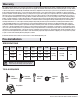
Pre-Installation (continued) HARDWARE INCLUDED NOTE: Hardware not shown to actual size.
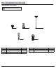
Pre-Installation (continued) PACKAGE CONTENTS A G B B H I C D J E K F Part Description L Quantity A Slide-on mounting bracket (inside canopy) 1 B Ball/downrod assembly C Part Description Quantity G Blade 5 H Blade bracket 5 1 I Light kit fitter assembly 1 Canopy with canopy ring attached 1 J Glass bowl 1 D Decorative motor collar cover 1 E Fan-motor assembly 1 K Remote control/receiver (batteries included) 1 F Light kit pan 1 L CFL light bulb, 14-Watt maximu
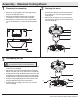
Installation MOUNTING OPTIONS WARNING: To reduce the risk of fire, electric shock or personal injury, mount to outlet box marked “acceptable for fan support of 35lbs. (15.9 Kg) or less” and use screws provided with the outlet box. An outlet box commonly used for the support of lighting fixtures may not be acceptable for fan support and may need to be replaced. If in doubt, consult a qualified electrician.
Assembly - Standard Ceiling Mount 1 2 Preparing for mounting □□ Remove the canopy ring (O) from the canopy (C) by turning □□ Route the wires exiting the top of the fan motor (E) into the decorative motor collar cover (D) and through the canopy ring (O). the ring to the right until it unlocks.
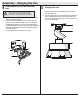
Assembly - Hanging the Fan 4 5 Attaching the fan to the electrical box WARNING: To reduce the risk of fire, electric shock or personal injury, mount to outlet box marked “acceptable for fan support of 35lbs. (15.9 Kg) or less” and use screws provided with the outlet box. □□ Carefully lift the fan-motor assembly (E) up to the slide-on mounting bracket (A). □□ Seat the hanger ball portion of the ball/downrod assembly (B) in the mounting bracket socket.
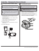
Assembly - Hanging the Fan (continued) 6 7 Setting the remote control codes NOTE: The frequencies on your receiver and remote control have been preset at the factory. Before installing the receiver, make sure the dip switches on the receiver and remote control are set to the same frequency. The dip switches on the remote control are located inside the battery compartment. Installing the receiver WARNING: To reduce the risk of fire or electric shock, remember to disconnect power.
Assembly - Hanging the Fan (continued) 8 9 Making the electrical connection WARNING: Each wire nut supplied with this fan is designed to accept up to one 12-gauge house wire and two wires from the fan. If you have larger than 12-gauge house wiring or more than one house wire to connect to the fan wiring, consult an electrician for the proper size wire nuts to use.
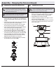
Assembly - Attaching the Fan Blades 10 11 Attaching the fan blades □□ Attach the blade assembly to the fan-motor assembly (E) NOTE: Your fan blades are reversible. Select the blade side finish which best accentuates your decor. □□ Attach the blade (G) to the blade bracket (H) using the blade □□ Attaching the blade assemblies □□ attachment screws (AA). Start a blade attachment screw (AA) into the blade bracket (H). Repeat for the two remaining blade attachment screws (AA).
Assembly - Attaching the Light Kit 12 13 Attaching the light kit pan □□ Remove one screw (P) from the light kit pan (F). Loosen, but CAUTION: To reduce the risk of electric shock, disconnect the electrical supply circuit to the fan before installing the light kit. □□ □□ Remove one screw (N) from the black bracket below the □□ Attaching the light kit fan-motor assembly (E). Loosen, but do not remove the other two screws.
Operation Warm weather - (Forward) A downward airflow creates a cooling effect. This allows you to set your air conditioner on a warmer setting without affecting your comfort. NOTE: The reverse switch is located at the top of motor housing. Shut the fan off and wait until the blades have completely stopped before flipping the switch to reverse the direction of your ceiling fan. Remote Control - Your fan is equipped with a remote control to operate the speed and lights of your new ceiling fan.
Care and Cleaning WARNING: Make sure the power is off before cleaning your fan. □□ Because of the fan’s natural movement, some connections may become loose. Check the support connections, brackets, and blade attachments twice a year. Make sure they are secure. It is not necessary to remove the fan from the ceiling. □□ Clean your fan periodically to help maintain its new appearance over the years.
Questions, problems, missing parts? Before returning to the store, call Hampton Bay Customer Service 8 a.m. - 6 p.m., EST, Monday-Friday 1-877-527-0313 HAMPTONBAY.COM Retain this manual for future use.
Artículo Núm. 610-015, 608-891 Modelo Núm. 51398, 51399 Modelo Núm. 52-MAL A probado por UL GUÍA DE USO Y MANTENIMIENTO VENTILADOR DE TECHO MARLOWE, DE 52 PLG (1,32 M) ¿Preguntas, problemas o piezas faltantes? Antes de regresar a la tienda, llama al Servicio al Cliente de Hampton Bay de Lunes a Viernes entre 8 a.m. y 6 p.m., (Hora del Este de EE. UU.) 1-877-527-0313 HAMPTONBAY.COM GRACIAS POR TU COMPRA Apreciamos la confianza que has depositado en Hampton Bay al comprar este ventilador de techo.
Tabla de Contenido Tabla de Contenido.............................................................. 2 Ensamblaje............................................................................ 7 Información de Seguridad................................................... 2 Funcionamiento.................................................................. 13 Garantía................................................................................. 3 Mantenimiento y Limpieza......................................
Garantía A partir de la fecha de compra por el comprador original, el proveedor garantiza de por vida, que el motor del ventilador no presenta defectos de fabricación ni de material desde la fecha de salida de la fábrica.
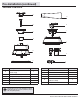
Preinstalación (continuación) HERRAJES INCLUIDOS NOTA: No se muestra el tamaño real de los herrajes.
Preinstalación (continuación) CONTENIDO DEL PAQUETE A G B B H I C D J E K F Pieza Descripción L Cantidad A Soporte de montaje deslizante (dentro de la cubierta) 1 B Ensamblaje de tubo bajante/bola 1 C Cubierta con aro incorporado 1 D Cubierta decorativa del collarín del motor 1 E Ensamblaje del motor del ventilador 1 F Carcasa del kit de luces 1 Pieza Descripción Cantidad G Aspa 5 H Soporte de aspa 5 I Ensamblaje del soporte del kit de luces 1 J Tazón de vidrio 1
Instalación OPCIONES DE MONTAJE NOTA: Tal vez necesites un tubo bajante más largo para mantener la altura mínima adecuada de las aspas, al instalar el ventilador en un techo inclinado. El ángulo máximo permitido es de 28º de la posición horizontal.
Ensamblaje – Montaje Estándar en Techo 1 2 Preparación para el montaje □□ Retira el aro (O) de la cubierta (C), girándolo hacia la derecha □□ Inserta los cables que salen por la parte superior del motor del ventilador (E) en la cubierta decorativa del collarín del motor (D) y a través del aro de la cubierta (O). □□ Asegúrate de que las aberturas en forma de ranura estén en la parte superior y, primero, inserta los cables por la cubierta (C), y luego a través del ensamblaje de tubo bajante/bola (B).
Ensamblaje – Cómo Colgar el Ventilador 4 5 Cómo fijar el ventilador a la caja eléctrica □□ Con cuidado alza el ensamblaje del motor del ventilador (E) ADVERTENCIA: Para reducir el riesgo de incendio, descarga eléctrica o lesiones personales, monta el ventilador sobre una caja eléctrica marcada como “aprobada como soporte de ventiladores de 35 lb (15,9 kg) o menos”, y usa los tornillos de montaje que vienen con la caja eléctrica. hasta el soporte de montaje deslizante (A).
Ensamblaje – Cómo Colgar el Ventilador (continuación) 6 7 Cómo configurar los códigos del control remoto Cómo instalar el receptor ADVERTENCIA: Para reducir el riesgo de incendio o de descarga eléctrica, recuerda desconectar la electricidad. El cableado eléctrico debe cumplir todos los requisitos del código nacional de electricidad y los códigos locales de electricidad. Las fuentes de energía y el ventilador deben ser de 110/120 V y 60 Hz.
Ensamblaje – Cómo Colgar el Ventilador (continuación) 8 9 Cómo hacer las conexiones eléctricas ADVERTENCIA: Cada cable no suministrado con este ventilador está diseñado para aceptar hasta un circuito eléctrico de casa de calibre 12 y dos cables del ventilador. Si tienes un cableado superior a calibre 12 o más de un cable para conectar al ventilador, consulta a un electricista para conocer el tamaño adecuado de las tuercas a usar.
Ensamblaje – Cómo Unir las Aspas del Ventilador 10 11 Cómo unir las aspas del ventilador NOTA:Las aspas de tu ventilador son reversibles. Elige el acabado del aspa que mejor resalte tu decoración. □□ Coloca el aspa en la carcasa del motor del ventilador (E) □□ Monta el aspa (G) al soporte de la misma (H) usando los □□ Cómo montar las aspas ensambladas □□ tornillos para montar las aspas (AA). Monta un tornillo para montar las aspas (AA) en el soporte del aspa (H).
Ensamblaje – Cómo Instalar el Kit de Luces 12 13 Cómo instalar la carcasa del kit de luces □□ Quita un tornillo (P) de la carcasa del kit de luces (F). Afloja los PRECAUCIÓN: Para disminuir el riesgo de descarga eléctrica, desconecta el circuito de energía del ventilador antes de instalar el kit de luces. □□ □□ Quita un tornillo (N) del soporte negro debajo del □□ Cómo instalar el kit de luces □□ ensamblaje del motor del ventilador (E). Afloja los otros dos tornillos, sin quitarlos.
Funcionamiento Clima cálido - (Hacia adelante) Un flujo de aire descendente crea un efecto de enfriamiento. Esto te permite fijar tu aire acondicionado en una configuración más alta sin afectar tu comodidad. NOTA: El interruptor de reversa está ubicado en la superficie de la carcasa del motor. Apaga el ventilador y espera hasta que las aspas se hayan detenido completamente antes de presionar el interruptor para invertir la dirección de tu ventilador de techo.
Mantenimiento y limpieza ADVERTENCIA: Asegúrate de que la corriente esté apagada antes de limpiar el ventilador. □□ Debido al movimiento natural del ventilador, algunas conexiones pueden aflojarse. Revisa las conexiones de soporte, soportes y accesorios de aspas dos veces al año. Verifica que estén seguros. No es necesario desmontar el ventilador del techo. □□ Limpia tu ventilador con frecuencia, para que luzca como nuevo con el paso de los años.
¿Preguntas, problemas o piezas faltantes? Antes de regresar a la tienda, llama al Servicio al Cliente de Hampton Bay de Lunes a Viernes entre 8 a.m. y 6 p.m., (Hora del Este de EE. UU.) 1-877-527-0313 HAMPTONBAY.COM Conserva este manual para uso en el futuro.