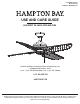
Item #1005 819 992 Model #52169 UL Model #EF200S(U)-52 USE AND CARE GUIDE HALPERT 52-INCH CEILING FAN Questions, problems, missing parts? Before returning to the store, call Hampton Bay Customer Service 8 a.m. - 7 p.m., EST, Monday-Friday, 9 a.m. - 6 p.m., EST, Saturday 1-855-HD-HAMPTON HAMPTONBAY.COM THANK YOU We appreciate the trust and confidence you have placed in Hampton Bay through the purchase of this ceiling fan. We strive to continually create quality products designed to enhance your home.
Table of Contents Table of Contents................................................................. 2 Assembly............................................................................... 7 Safety Information................................................................ 2 Operation............................................................................ 12 Warranty................................................................................ 3 Care and Cleaning................................
Warranty The supplier warrants the fan motor to be free from defects in workmanship and material present at time of shipment from the factory for a lifetime after the date of purchase by the original purchaser. The supplier warrants that the light kit, excluding any glass, to be free from defects in workmanship and material at the time of shipment from the factory for a period of three years after the date of purchase by the original purchaser.
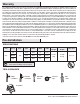
Pre-Installation (continued) HARDWARE INCLUDED NOTE: Hardware not shown to actual size.
Pre-Installation (continued) PACKAGE CONTENTS A B H C D E F I G Part Description Quantity A Slide-on mounting bracket (inside canopy) 1 B Canopy C Part Description Quantity F Fan-motor assembly 1 G Switch cup cover 1 1 H Blade 4 Canopy bottom cover 1 I Blade bracket 4 D Ball/downrod assembly 1 E Coupler cover 1 IMPORTANT: This product and/or components are governed by one or more of the following U.S.
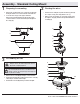
Installation MOUNTING OPTIONS NOTE: You may need a longer downrod to maintain proper blade clearance when installing on a steep, sloped ceiling. The maximum angle allowable is 30° away from horizontal. WARNING: To reduce the risk of fire, electric shock or personal injury, mount to outlet box marked “Acceptable for fan support of 35 lbs. (15.9 Kg) or less”, and use screws provided with the outlet box.
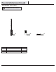
Assembly - Standard Ceiling Mount 1 2 Preparing for mounting □ Remove the canopy bottom cover (C) from the canopy (B) by □ □ turning the bottom cover counterclockwise until it unlocks. Loosen the two canopy screws (FF) located in the bottom of the mounting bracket (A), and turn the canopy counterclockwise to remove the mounting bracket (A) from the canopy (B). □ Routing the wires Route the wires exiting the top of the fan motor (F), through the coupler cover (E) and canopy bottom cover (C).
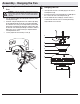
Assembly - Hanging the Fan 1 2 Attaching the fan to the electrical box □ Carefully lift the fan-motor assembly (E) up to the slide-on WARNING: To reduce the risk of fire, electric shock or personal injury, mount to outlet box marked “Acceptable for fan support of 35 lbs. (15.9 Kg) or less”, and use screws provided with the outlet box. mounting bracket (A). □ Insert the ball portion of the ball/downrod assembly (D) into the socket of the slide-on mounting bracket (A).
Assembly - Hanging the Fan (continued) 3 4 Making the electrical connection WARNING: Remove the rubber motor stops on the bottom of the fan before installing the blades or testing the motor. Wrapping the extra wire NOTE: Follow this step ONLY if you did not cut the extra length off from the wires coming from the ceiling fan. IMPORTANT: Use the wire connecting nuts (BB) supplied with your fan. Secure the connectors with electrical tape and ensure there are no loose strands or connections.
Assembly - Hanging the Fan (continued) 5 Mounting the fan WARNING: When using the standard ball/downrod mounting, the tab in the ring at the bottom of the mounting bracket must rest in the groove of the hanger ball. Failure to properly seat the tab in the groove could cause damage to the wiring. EE □ Align the locking slots of the ceiling canopy (B) with the two □ □ A screws (FF) and alignment posts (EE) in the mounting bracket (A). Push up to engage the slots and turn clockwise to lock in place.
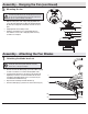
Assembly - Attaching the Fan Blades (continued) 2 Attaching the fan blades NOTE: Your fan features revolutionary advancements for quick and easy blade installation. □ Mount the fan blades (H) to the blade bracket (I) by aligning □ □ □ □ □ the three key-slot holes in the blade (H) with the three posts on the top of the blade brackets (I). Hold the blade (H) close to the blade bracket (I) and press the blade (H) down firmly. Ensure the key-slot holes are properly seated on the blade arm posts.
Operation Turn on the power and check the operation of the fan. The pull chain controls the fan speeds as follows: 1 pull - High, 2 pulls - Medium, 3 pulls - Low, 4 pulls - Off A. Warm weather The appropriate speed settings for warm or cool weather depends on factors such as the room size, ceiling height, and number of fans. The fan is shipped from the factory with the reversing switch positioned to circulate air downward.
Care and Cleaning WARNING: Make sure the power is off before cleaning your fan. □ Because of the fan’s natural movement, some connections may become loose. Check the support connections, brackets, and blade attachments twice a year. Make sure they are secure. It is not necessary to remove the fan from the ceiling. □ Clean your fan periodically to help maintain its new appearance over the years.
Questions, problems, missing parts? Before returning to the store, call Hampton Bay Customer Service 8 a.m. - 7 p.m., EST, Monday-Friday, 9 a.m. - 6 p.m., EST, Saturday 1-855-HD-HAMPTON HAMPTONBAY.COM Retain this manual for future use.