Item # 987-787 Model #52356 UL Model #60-ATO USE AND CARE GUIDE ALTURA 60-INCH CEILING FAN Questions, problems, missing parts? Before returning to the store, call Hampton Bay Customer Service 8 a.m. - 6 p.m., EST, Monday-Friday. 1-877-527-0313 HAMPTONBAY.COM THANK YOU We appreciate the trust and confidence you have placed in Hampton Bay through the purchase of this ceiling fan. We strive to continually create quality products designed to enhance your home.
Table of Contents Table of Contents................................................................. 2 Assembly............................................................................... 7 Safety Information................................................................ 2 Operation............................................................................ 12 Warranty................................................................................ 3 Care and Cleaning................................
Warranty The supplier warrants the fan motor to be free from defects in workmanship and material present at time of shipment from the factory for a lifetime after the date of purchase by the original purchaser. The supplier also warrants that all other fan parts, excluding any glass or acrylic blades, to be free from defects in workmanship and material at the time of shipment from the factory for a period of two years after the date of purchase by the original purchaser.
Pre-installation (continued) HARDWARE INCLUDED NOTE: Hardware not shown to actual size.
Pre-installation (continued) PACKAGE CONTENTS A F B G B C H 3 2 1 0 I D E Part Description Quantity A Slide-on mounting bracket (inside canopy) 1 B Ball/downrod assembly C Part Description Quantity F Decorative motor collar cover 1 G Blade 5 1 H Switch cup adaptor 1 Canopy with canopy ring attached 1 I Wall control 1 D Fan-motor assembly 1 E Switch cup 1 IMPORTANT: This product and/or components are governed by one or more of the following U.S.
Installation MOUNTING OPTIONS NOTE: You may need a longer downrod to maintain proper blade clearance when installing on a steep, sloped ceiling. The maximum angle allowable is 30° away from horizontal. WARNING: To reduce the risk of fire, electric shock or personal injury, mount to outlet box marked “Acceptable for fan support of 50lbs. (22.7 Kg) or less”, and use screws provided with the outlet box.
Assembly - Standard Ceiling Mount 1 2 Preparing for mounting □□ Remove the canopy ring (L) from the canopy (C) by turning □□ □□ Routing the wires □□ Route the wires exiting the top of the fan motor (D) into the decorative motor collar cover (F) and through the canopy ring (L). the ring to the right until it unlocks. Remove the mounting bracket (A) from the canopy (C) by loosening the four screws (SS) on the top of the canopy (C). Remove the two non-slotted screws, and loosen the slotted screws.
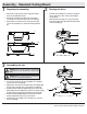
Assembly - Hanging the Fan 4 5 Attaching the fan to the electrical box □□ Carefully lift the fan motor assembly (D) up to the slide-on WARNING: To reduce the risk of fire, electric shock or personal injury, mount to outlet box marked “Acceptable for fan support of 50lbs. (22.7 Kg) or less”, and use screws provided with the outlet box. mounting bracket (A). □□ Seat the hanger ball portion of the ball/downrod assembly (B) in the mounting bracket (A) socket.
Assembly - Hanging the Fan (continued) WARNING: Each wire nut supplied with this fan is designed to accept up to one 12-gauge house wire and two wires from the fan. If you have larger than 12-gauge house wiring or more than one house wire to connect to the fan wiring, consult an electrician for the proper size wire nuts to use. LL Making the electrical connection KK 6 MM JJ KK LL II IMPORTANT: Use the plastic wire connecting nuts (BB) supplied with your fan.
Assembly - Hanging the Fan (continued) 7 8 Mounting the fan □□ Attach blade (G) to blade bracket (J) using the decorative WARNING: When using the standard ball/downrod mounting, the tab in the ring at the bottom of the mounting bracket must rest in the groove of the hanger ball. Failure to properly seat the tab in the groove could cause damage to the wiring. □□ Align the locking slots of the ceiling canopy (C) with the two □□ □□ □□ □□ □□ screws (SS) in the slide-on mounting bracket (A).
Assembly - Attaching the accessories 9 10 Attaching the switch cup adaptor □□ Remove the three screws from the black bracket below the □□ □□ □□ Attaching the switch cup CAUTION: To reduce the risk of electric shock, disconnect the electrical supply circuit to the fan before installing the switch cup. fan motor assembly (D). Align the key holes in the switch cup adaptor (H) with the three holes in the black bracket. Re-install the three screws that were removed in first step.
Operating Your Fan and Wall Control Wall Control - Your fan is equipped with a wall control to operate the speed of your new ceiling fan. For more information on how to install the wall control, see the wall control instructions packaged with the wall control components. Wall control installation WARNING: To avoid possible electrical shock, be sure electricity is turned off at the main fuse or circuit breaker box before wiring. Turning off the wall switch is not sufcient to prevent shock.
Care and Cleaning WARNING: Make sure the power is off before cleaning your fan. □□ Because of the fan’s natural movement, some connections may become loose. Check the support connections, brackets, and blade attachments twice a year. Make sure they are secure. It is not necessary to remove the fan from the ceiling. □□ Clean your fan periodically to help maintain its new appearance over the years.
Questions, problems, missing parts? Before returning to the store, call Hampton Bay Customer Service 8 a.m. - 6 p.m., EST, Monday-Friday 1-877-527-0313 HAMPTONBAY.COM Retain this manual for future use.
Artículo Núm. 987-787 Modelo Núm. 52356 Modelo Núm. 60-ATO aprobado por UL GUÍA DE USO Y MANTENIMIENTO VENTILADOR DE TECHO ALTURA, DE 1,52 M ¿Preguntas, problemas o piezas faltantes? Antes de regresar a la tienda, llama al Servicio al Cliente de Hampton Bay de Lunes a Viernes entre 8 a.m. y 6 p.m., (hora Estándar del Este de EE. UU.) 1-877-527-0313 HAMPTONBAY.COM GRACIAS POR TU COMPRA Apreciamos la confianza que has depositado en Hampton Bay al comprar este ventilador de techo.
Tabla de Contenido Tabla de Contenido.............................................................. 2 Ensamblaje............................................................................ 7 Información de Seguridad................................................... 2 Funcionamiento.................................................................. 12 Garantía................................................................................. 3 Mantenimiento y Limpieza......................................
Garantía El proveedor garantiza de por vida, a partir de la fecha en que el comprador original lo adquiere, que el motor del ventilador no presenta defectos de fabricación ni de material al momento en que es enviado desde la fábrica.
Pre-instalación (continuación) HERRAJES INCLUIDOS NOTA: No se muestra el tamaño real de los herrajes.
Pre-instalación (continuación) CONTENIDO DEL PAQUETE A F B G B C H 3 2 1 0 I D E Pieza Descripción Cantidad A Soporte deslizante de montaje (dentro de la cubierta) 1 B Ensamblaje de tubo bajante/bola C Pieza Descripción Cantidad F Cubierta decorativa del collarín del motor 1 1 G Aspa 5 Cubierta con aro incorporado 1 H Adaptador de la caja del interruptor 1 D Ensamblaje del motor del ventilador 1 I Control de pared 1 E Caja del interruptor (receptor incluido) 1 IMPO
Instalación OPCIONES DE MONTAJE NOTA:Tal vez necesites un tubo bajante más largo para mantener la altura mínima adecuada de las aspas, al instalar el ventilador en un techo inclinado. El ángulo máximo permitido es de 30º de la posición horizontal.
Ensamblaje - Montaje Estándar en Techo 1 2 Preparación para el montaje □□ Retira el aro (L) de la cubierta (C), girándolo hacia la derecha □□ □□ Disposición de los cables □□ Inserta los cables que salen por la parte superior del motor del ventilador (D) en la cubierta decorativa del collarín del motor (F) y a través del aro de la cubierta (L). hasta soltarlo. Retira el soporte de montaje (A) de la cubierta (C) aflojando los cuatro tornillos (SS) en la parte superior de la cubierta (C).
Ensamblaje - Cómo Colgar el Ventilador 4 5 Cómo conectar el ventilador con la caja eléctrica □□ Con cuidado alza el ensamblaje del motor del ventilador (D) ADVERTENCIA: Para reducir el riesgo de incendio, descarga eléctrica o lesiones personales, monta el ventilador sobre una caja eléctrica marcada como “aprobada como soporte de ventiladores de 50 lb (22,7kg) o menos”, y usa los tornillos de montaje que vienen con la misma. hasta el soporte de montaje deslizante (A).
Ensamblaje — Cómo Colgar el Ventilador (continuación) ADVERTENCIA: Cada tuerca para cable incluida con este ventilador está diseñada para sostener cables domésticos de calibre máximo de 12 y dos cables del ventilador. Si tienes un cableado doméstico de calibre superior a 12 o vas a conectar más de un cable doméstico al sistema de cableado del ventilador, consulta con un electricista acerca del tamaño adecuado de las tuercas para cable.
Ensamblaje — Cómo Colgar el Ventilador (continuación) 7 8 Cómo montar el ventilador □□ Monta el aspa (G) al soporte de la misma (J) usando las ADVERTENCIA: Cuando uses el ensamblaje del tubo bajante/ bola estándar, la pestaña en el aro en la parte inferior del soporte de montaje debe encajar en la ranura de la bola de soporte. Si la pestaña no se asienta correctamente en la ranura, se puede dañar el cableado.
Ensamblaje — Cómo montar los accesorios 9 10 Cómo instalar el adaptador de la caja del interruptor □□ Quita los tres tornillos del soporte negro debajo del □□ □□ Cómo instalar la caja del interruptor PRECAUCIÓN: Para disminuir el riesgo de descarga eléctrica, desconecta el circuito de energía del ventilador antes de instalar la caja del interruptor. ensamblado del motor del ventilador (D).
Funcionamiento Instalación del control de pared Control de Pared - Tu ventilador está equipado con un control de pared que controla la velocidad de tu nuevo ventilador de techo. Para más información sobre cómo instalar el control de pared, consulta las instrucciones del control de pared y revisa los componentes incluidos con el mismo. Las conguraciones de velocidad para clima cálido o frío dependen de factores como tamaño de la habitación, altura del techo y cantidad de ventiladores.
Mantenimiento y Limpieza ADVERTENCIA: Asegúrate de que la corriente esté apagada antes de limpiar el ventilador. □□ Debido al movimiento natural del ventilador, algunas conexiones pueden aflojarse. Revisa las conexiones de soporte, los soportes y accesorios de aspas dos veces al año. Verifica que estén bien asegurados. No es necesario desmontar el ventilador del techo. □□ Limpia tu ventilador con frecuencia para que luzca como nuevo a pesar de los años.
¿Preguntas, problemas o piezas faltantes? Antes de regresar a la tienda, llama al Servicio al Cliente de Hampton Bay de Lunes a Viernes entre 8 a.m. y 6 p.m., (hora Estándar del Este de EE. UU.) 1-877-527-0313 HAMPTONBAY.COM Conserva este manual para uso en el futuro.