
Installation Guide

10
Assembly - Hanging the Fan (continued)
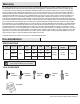
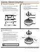
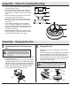
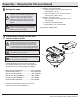
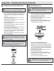
Making the electrical connection Mounting the fan
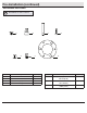
Close-to-Ceiling Mounting
□ Connect the two green fan wires (II) to the household wire (II).
□ If you are using the optional light kit, connect the blue fan
wire (JJ) and the black fan wire (KK) to the black household
wire (KK).
□ Connect the fan motor white wire (LL) to the receiver (PP)
white wire (LL) using a wire nut.
□ Connect the fan motor black wire (KK) to the receiver (PP)
black wire (KK) using a wire nut.
□ Connect the fan motor blue wire (JJ) to the receiver (PP) blue
wire (JJ) using a wire nut.
□ Connect the receiver (PP) red wire (OO) to the supply black
(hot) wire (KK) using a wire nut.
□ Connect the receiver (PP) white wire (LL) to the supply white
wire (neutral) (LL) wire using a wire nut.
□ Spread the wires apart so that the green (II) and white (LL)
wires are on the side of the outlet box (MM) and the black
wire (KK) is on the other side.
□ Turn the wire connecting nuts upward and push the wiring
into the outlet box (MM).
□ Align the locking slots of the ceiling canopy (C) with the two
screws in the mounting bracket (A). Push up to engage the
slots and turn clockwise to lock in place.
□ Firmly tighten the two mounting screws.
□ Install the remaining two mounting screws into the holes in
the canopy (C) and tighten rmly.
□ Install the decorative canopy ring by aligning the ring’s
slots with the screws in the canopy (C). Rotate the ring
counter-clockwise to lock in place.
□ Carefully unhook the fan from the mounting bracket (A) and
align the locking slots of the ceiling canopy (C) with the two
screws in the mounting bracket (A). Push up to engage the
slots and turn clockwise to lock in place. Immediately tighten
the two mounting screws rmly.
□ Install the remaining two mounting screws into the holes in
the canopy (C) and tighten rmly.
□ Install the decorative canopy ring by aligning the ring’s
slots with the screws in the canopy (C). Rotate the ring
counter-clockwise to lock in place.
□ You may now proceed to attaching the fan blades.
8 9
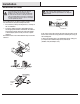
IMPORTANT: Use the wire connecting nuts supplied with
your fan. Secure the connectors with electrical tape and
ensure there are no loose strands or connections.
NOTE: The frequencies on your receiver and transmitter have been
preset at the factory. Before installing the receiver, make sure the
dip switches on the receiver and transmitter are set to the same
frequency. The dip switches on the transmitter are located inside
the battery compartment.
WARNING: Each wire not supplied with this fan is designed to
accept up to one 12-gauge house wire and two wires from the
fan. If you have larger than 12-gauge house wiring or more
than one house wire to connect to the fan wiring, consult an
electrician for the proper size wire nuts to use.
WARNING: When using the standard ball/downrod mounting, the
tab in the ring at the bottom of the mounting bracket must rest in
the groove of the hanger ball. Failure to properly seat the tab in
the groove could cause damage to the wiring.
JJ
KK
LL
LL
JJ
KK
LL
II
MM
KK
LL
PP
OO
LL
A
C
WARNING: Locking slots of celling canopy are provided only as an
aid to mounting. Do not leave fan assembly undattended until all
four canopy screws are engaged and rmly tightened.