
Installation Guide

9
HAMPTONBAY.COM
Please contact 1-877-527-0313 for further assistance.
Assembly - Hanging the Fan (continued)
6
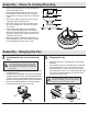
NOTE: The battery will weaken with age and should be
replaced before leaking takes place as this will damage
the hand unit. Dispose of used battery properly and keep
the battery out of the reach of children.
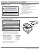
Setting the code
NOTE: This remote is equipped with 16 code
combination. To prevent possible interference from or
to other remote units such as garage door openers,
car alarm or security system, simply change the
combination code but be sure that the code on both
the hand held transmitter and receiver in the fan are
matched.
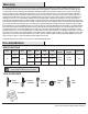
□ Setting the code on the transmitter
a. Remove the battery cover. Press rmly below arrow
and slide battery cover off.
b. Slide code switches to your choice of up or down
position. (factory setting is all up).
□ Setting the code on the receiver
a. Slide code switches to the same position as set on
your transmitter.
b. Install the 9 volt battery (included)
c. Replace battery cover on the transmitter.
Controller Model: FAN28R-240W
7
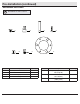
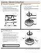
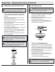
Installing the receiver for use with
remote control option
□ Position the supply wires to the left side of the slide-on
mounting bracket (A); position the fan wires to the right
side. Partially insert the remote control receiver (I) (at side
up) until one end rests on the ball/downrod assembly (B).
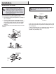
WARNING: To reduce the risk of re or electric shock,
remember to disconnect power. The electrical wiring must
meet all local and national electrical code requirements.
The electrical source and fan must be 110/120 volt, 60Hz.
Do not use this product in conjunction with any variable wall
control. Incorrect wire connection can damage this receiver.
CAUTION: If other fan wires are a different color, have this
unit installed by a licensed electrician.
CAUTION: Do not install in a damp location or immerse
in water (For indoor use only). Do not pull on or cut leads
shorter. Do not drop or bump the unit.
A
B
I
□ Wire Connection: Fan Green Wire...........................Bare Supply Wire
Red Receiver Wire (AC IN L)...................................Black Supply Wire
White Receiver Wire (AC IN N)................................White Supply Wire
White Receiver Wire (TO MOTOR N)........................White Fan Wire
Black Receiver Wire (TO MOTOR L).........................Black Fan Wire
Blue Receiver Wire (FOR LIGHT).............................Blue Light Wire
□ Lay the brown antenna wire on top of the receiver, and
slide the receiver into the mounting bracket.