Item # 434-940, 434-972, 526-012 Model # 52869, 26829, 52860 USE AND CARE GUIDE INDUSTRIAL 60-INCH CEILING FAN Questions, problems, missing parts? Before returning to the store, call Hampton Bay Customer Service 8 a.m. - 6 p.m., EST, Monday-Friday. 1-877-527-0313 HAMPTONBAY.COM THANK YOU We appreciate the trust and confidence you have placed in Hampton Bay through the purchase of this ceiling fan. We strive to continually create quality products designed to enhance your home.
Table of Contents Table of Contents................................................................. 2 Assembly............................................................................... 7 Safety Information................................................................ 2 Operation............................................................................ 12 Warranty................................................................................ 3 Care and Cleaning................................
Warranty The supplier warrants the fan motor to be free from defects in workmanship and material present at time of shipment from the factory for a lifetime after the date of purchase by the original purchaser. The supplier also warrants that all other fan parts, excluding any glass or acrylic blades, to be free from defects in workmanship and material at the time of shipment from the factory for a period of two years after the date of purchase by the original purchaser.
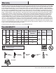
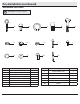
Pre-Installation (continued) HARDWARE INCLUDED NOTE: Hardware not shown to actual size.
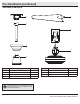
Pre-Installation (continued) PACKAGE CONTENTS A E B F C G D Part Description Quantity Part Description Quantity A Mounting bracket 1 E Blade 3 B Ball/downrod assembly 1 F Wall control 1 C Canopy 1 G Motor 1 D Coupler cover 1 IMPORTANT: This product and/or components are governed by one or more of the following U.S. Patents: 5,947,436; 5,988,580; 6,010,110; 6,046,416, 6,210,117 and other patents pending. 5 HAMPTONBAY.
Installation MOUNTING OPTIONS WARNING: To reduce the risk of fire, electric shock or personal injury, mount to outlet box marked “Acceptable for fan support of 35lbs. (15.9 Kg) or less”, and use screws provided with the outlet box. An outlet box commonly used for the support of lighting fixtures may not be acceptable for fan support and may need to be replaced. If in doubt, consult a qualified electrician.
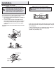
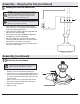
Assembly 1 2 Dismantling the ball/downrod assembly Installing the downrod □□ Route the wires exiting the top of the motor housing (G) □□ Loosen the hanger ball (H) by removing the set screw (PP) and lockwasher (QQ) at the top of the downrod (B) which holds the hanger ball to the downrod. □□ Slide the hanger ball (H) down the downrod (B) and remove the support pin (RR). □□ Unscrew the green groundwire (I) located at the top of the downrod (B) by unscrewing the screw (SS) on the downrod (B).
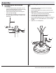
Assembly (continued) 3 4 Installing the coupler cover and canopy □□ Slide the coupler cover (D) onto the downrod (B) and push the □□ □□ Installing the ball on the downrod □□ Slide the hanger ball (H) onto the top of the downrod (B) past the holes in the downrod (B). □□ Replace the support pin (RR) into the holes located at the top of the downrod (B). □□ Slide the ball (H) up and align the holes in the ball (H) and downrod (B). Make sure the support pin (RR) aligns in the slot of the ball (H).
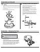
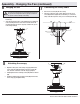
Assembly - Hanging the Fan (continued) 6 7 Hanging the fan □□ Turn the wood screw (AA) into the ceiling. □□ Place the looped end of the safety cable (K) onto the wood WARNING: When using the standard ball/downrod mounting, the tab in the ring at the bottom of the mounting bracket must rest in the groove of the hanger ball. Failure to properly seat the tab in the groove could cause damage to the wiring.
Assembly - Hanging the Fan (continued) 9 VV WARNING: Each wire not supplied with this fan is designed to accept up to one 12-gauge house wire and two wires from the fan. If you have larger than 12-gauge house wiring or more than one house wire to connect to the fan wiring, consult an electrician for the proper size wire nuts to use. UU Making the electrical connection WW XX □□ □□ □□ □□ WW WW may be a bare wire or a wire with green colored insulation) to the green ground lead(s) (UU) of the fan.
Operation Install 4-speed wall control See the instructions enclosed with the wall control package. Operating your fan NOTE: Wait for the fan to completely stop before setting the slide switch to reverse the direction of blade rotation. The reverse switch is located on the coupler (J). To switch the direction of the blade rotation, follow the instructions below. □□ Loosen the set screw (MM) on the coupler cover (D). □□ Slide coupler cover (D) up to reveal the coupler (J) and reverse switch (YY).
Care and Cleaning WARNING: Make sure the power is off before cleaning your fan. □□ Because of the fan’s natural movement, some connections may become loose. Check the support connections, brackets, and blade attachments twice a year. Make sure they are secure. It is not necessary to remove the fan from the ceiling. □□ Clean your fan periodically to help maintain its new appearance over the years.
Questions, problems, missing parts? Before returning to the store, call Hampton Bay Customer Service 8 a.m. - 6 p.m., EST, Monday-Friday 1-877-527-0313 HAMPTONBAY.COM Retain this manual for future use.
Artículo Núm. 434-940, 434-972, 526-012 Modelo Núm. 52869, 26629, 52860 GUÍA DE USO Y MANTENIMIENTO VENTILADOR DE TECHO, INDUSTRIAL, DE 1,72 M ¿Preguntas, problemas o piezas faltantes? Antes de regresar a la tienda, llama al Servicio al Cliente de Hampton Bay de Lunes a Viernes entre 8 a.m. y 6 p.m., (hora del Este de EE. UU.) 1-877-527-0313 HOMEDEPOT.COM GRACIAS POR TU COMPRA Apreciamos la confianza que has depositado en Hampton Bay al comprar este ventilador de techo.
Tabla de Contenido Tabla de Contenido.............................................................. 2 Ensamblaje............................................................................ 7 Información de Seguridad................................................... 2 Funcionamiento.................................................................. 12 Garantía................................................................................. 3 Mantenimiento y Limpieza......................................
Garantía El proveedor garantiza de por vida, a partir de la fecha en que el comprador original lo adquiere, que el motor del ventilador no presenta defectos de fabricación ni de material al momento en que es enviado desde la fábrica.
Pre-Instalación (continuación) HERRAJES INCLUIDOS NOTA: No se muestra el tamaño real de los herrajes.
Pre-Instalación (continuación) CONTENIDO DEL PAQUETE A E B F C G D Pieza Descripción Cantidad Pieza Descripción Cantidad A Soporte de montaje 1 E Aspa 3 B Ensamblaje de tubo bajante/bola 1 F Control de pared 1 C Cubierta 1 G Motor 1 D Tapa del acoplador 1 IMPORTANTE: Este producto y/o sus componentes están protegidos por una o más de las siguientes Patentes: 5,947,436; 5,988,580; 6,010,110; 6,046,416, 6,210,117 y otras patentes pendientes. 5 HOMEDEPOT.
Instalación OPCIONES DE MONTAJE NOTA:Tal vez necesites un tubo bajante más largo para mantener la altura mínima adecuada de las aspas, al instalar el ventilador en un techo inclinado. El ángulo máximo permitido es de 30º de la posición horizontal.
Ensamblaje 1 2 Cómo desmantelar el ensamblaje del tubo bajante/bola Cómo instalar el tubo bajante □□ Inserta los cables que salen por la parte superior de la carcasa □□ Afloja la bola de soporte (H) quitando el tornillo de ajuste (PP) y la arandela de seguridad (QQ) en la parte superior del tubo bajante (B) que sujeta la bola de soporte hasta el tubo bajante. □□ Desliza la bola de soporte (H) por el tubo bajante (B) y retira el pasador de soporte (RR).
Ensamblaje (continuación) 3 4 Cómo instalar la tapa del acoplador y la cubierta □□ Coloca la tapa del acoplador (D) en el tubo bajante (B) □□ □□ Cómo instalar la bola en el tubo bajante □□ Desliza la bola de soporte (H) en la parte superior del tubo bajante (B), pasando los orificios en el tubo bajante (B). □□ Vuelve a colocar el pasador de soporte (RR) en los orificios del extremo superior del tubo bajante (B).
Ensamblaje — Colgar el Ventilador (continuación) 6 7 Cómo colgar el ventilador Cómo conectar el cable de seguridad □□ Enrosca el tornillo para madera (AA) en el techo. □□ Coloca el extremo en bucle del cable de seguridad (K) sobre ADVERTENCIA: Cuando uses el montaje de tubo bajante y bola estándar, la pestaña en el aro en la parte inferior del soporte de montaje debe encajar en la ranura de la bola de soporte. Si la pestaña no se asienta correctamente en la ranura, se puede dañar el cableado.
Ensamblaje — Colgar el Ventilador (continuación) 9 VV ADVERTENCIA: Cada cable no suministrado con este ventilador está diseñado para aceptar un máximo de un solo circuito eléctrico doméstico de calibre 12 y dos cables del ventilador. Si tienes un cableado doméstico de calibre superior a 12 o más de un cable doméstico para conectar el cableado del ventilador, consulta a un electricista para el tamaño adecuado de tuercas de cable.
Funcionamiento Instala el control de pared de 4 velocidades Ver las instrucciones incluidas en el paquete del control de pared. Cómo operar el ventilador NOTA: Espera a que se detenga completamente el ventilador antes de colocar el interruptor deslizante para invertir la dirección de giro de las aspas. MM El interruptor de reversa está ubicado en la superficie del acoplador (J). Para invertir la dirección de giro de las aspas, sigue las instrucciones a continuación.
Mantenimiento y Limpieza ADVERTENCIA: Asegúrate de que la corriente esté apagada antes de limpiar el ventilador. □□ Debido al movimiento natural del ventilador, algunas conexiones pueden aflojarse. Revisa las conexiones de soporte, soportes y accesorios de aspas dos veces al año. Verifica que estén seguros. No es necesario desmontar el ventilador del techo. □□ Limpia tu ventilador con frecuencia, para que luzca como nuevo a pesar de los años.
¿Preguntas, problemas o piezas faltantes? Antes de regresar a la tienda, llama al Servicio al Cliente de Hampton Bay de Lunes a Viernes entre 8 a.m. y 6 p.m., (hora del Este de EE. UU.) 1-877-527-0313 HOMEDEPOT.COM Conserva este manual para uso en el futuro.