
Use and Care Guide


11
HAMPTONBAY.COM
Please contact 1-855-HD-HAMPTON for further assistance.
Making the electrical connections
□
If using the 4.5 in. ball downrod assembly (B) provided,
wire the receiver to the fan wires by connecting the molded
adaptor plug from receiver (K) with molded adaptor of the fan
motor assembly (D) together.
□
If you wish to use longer downrod, you can use the extension
lead wire (42 in.) (O) provided by connecting the molded
adaptor together.
6
Assembly - Hanging the Fan (continued)
NOTE: The fan comes with 12 in. lead wires for use with the
provided 4.5 in. ball downrod assembly (B), if you wish to use
longer downrod, you can use the extension lead wire (42 in.) (O)
provided.
Outlet box
in the ceiling
(MM)
Green
1 2 3 4
ON
DIP
O
J
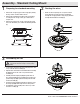
Mounting the fan-motor assembly
(standard mount)
□
Align the locking slots of the ceiling canopy (C) with the two
screws in the mounting bracket (A). Push up to engage the
slots and turn clockwise to lock in place.
□
Firmly tighten the two mounting screws.
□
Install the two mounting screws (saved from Assembly Step 1
“Preparing for mounting”) into the holes in the canopy (C) and
tighten rmly.
□
Install the decorative canopy ring (L) by aligning the ring’s
slots with the screws in the canopy (C). Rotate the ring
clockwise to lock in place.
7
WARNING: When using the standard ball/downrod mounting, the
tab in the ring at the bottom of the mounting bracket must rest in
the groove of the hanger ball. Failure to properly seat the tab in
the groove could cause damage to the wiring.
WARNING: The locking slots of ceiling canopy are provided only
as an aid to mounting. Do not leave the fan assembly unattended
until all four canopy screws are engaged and rmly tightened.
D
C
A
JJ
L