Item #1001-419-054 Model #7114-01 USE AND CARE GUIDE NO CUT EASY INSTALL VENTILATION FAN Questions, problems, missing parts? Before returning to the store, call Hampton Bay Customer Service 8 a.m. - 7 p.m., EST, Monday-Friday, 9 a.m. - 6 p.m., EST Saturday 1-855-HD-HAMPTON HAMPTONBAY.COM THANK YOU We appreciate the trust and confidence you have placed in Hampton Bay through the purchase of this ventilating bath fan. We strive to continually create quality products designed to enhance your home.
Table of Contents Table of Contents............................................................ 2 Safety Information........................................................... 2 Product Specifications.................................................... 3 Typical Installation........................................................... 3 Wiring Diagram................................................................ 3 Quick connector instructions.................................................... 3 Warranty...
Product Specification SPECIFICATIONS Airflow: 50 CFM SPECIFICATIONS Power consumption: 8.0 W 120 V, 60 Hz Weight: 3.65 lbs. Duct diameter: 3 in. Ceiling Opening Dimension Requirements: 7-1/2 in. (L) x 7-1/4 in. (W) x 4 in. (H) Sound output: 1.0 Sone Typical Installation The ducting from this fan to the outside of the building has a strong effect on the air flow, noise and energy use of the fan.
Warranty LIMITED LIFETIME WARRANTY WHAT IS COVERED If this product fails due to a defect in materials or workmanship at any time during the first FIVE years of ownership, the manufacturer will replace it free of charge, postage-paid at their option. This warranty does not cover products that have been abused, altered, damaged, misused, cut or worn. This warranty does not cover use in commercial applications. Use only manufacturer-supplied genuine warranty repair replacement parts to repair this fan.
Pre-installation (continued) PACKAGE CONTENTS A C D B Part Description Quantity A B C D Fan housing Grille Duct connector Long wood screws (ø4x25mm) 1 1 1 3 5 HAMPTONBAY.COM Please contact 1-855-HD-HAMPTON for further assistance.
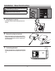
Installation - New Construction CAUTION: Make sure power is switched off at service panel before starting installation. NOTE: Unit can be mounted in a ceiling or wall. 1 2 3 Attaching duct connector Attach duct connector to the fan housing as shown in the drawing. Remove the wiring box knockout Remove the wiring box cover from the fan housing with a Phillips head screwdriver (not included). Remove the wiring knockout from the wiring box cover with a flathead screwdriver (not included).
Installation - New Construction (continued) 4 Mount the fan housing 5 Connect house and fan wires Ceiling joist M ount the fan housing to the joist using two long wood screws (D) where indicated. Black (Live) White (Neutral) Green (Ground) Pull the wire through the hole and into the junction box (not included). Using a quick connector, secure 120 VAC house wiring from the wall switch to the fan as shown in the wiring diagram on the right.
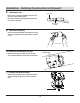
Installation - Existing Construction CAUTION: Turn off electricity at breaker box before beginning installation. Review all safety precautions. 1 Remove the existing fan 2 Measure the ceiling opening Remove the old fan from the ceiling. easure the opening to assure it is large enough to accomM modate the new fan body (A) (7.50 in. x 7.25 in.). NOTE: 7.25 inch side of the opening should be flush with the joist.
Installation - Existing Construction (continued) 4 5 Attaching duct connector Attach duct connector to the fan housing as shown in the drawing. Remove the fan motor assembly emove the three screws (1) that hold the fan motor assembly R in place. Remove the fan motor assembly from the fan housing. Unplug the fan power unit. 1 6 7 Remove the wiring box knockout Remove the wiring box cover from the fan housing.
Installation - Existing Construction (continued) 8 Installing the duct Install a circular 3 in. duct (not included) and secure it with duct tape or clamps (neither included). Finish ceiling work. The ceiling hole should be aligned with the edge of the fan housing. 3 in. duct Duct tape or clamp 9 Insert the fan housing Insert the fan housing through the existing hole in the ceiling. The fan housing should be level and perpendicular to the joist or stud.
Installation - Existing Construction (continued) 12 Install the grille Pinch the mounting springs on the grille (B) and insert them into the narrow rectangular slots inside the fan. Push the grille (B) up toward the ceiling. Turn on electricity at the breaker box after finishing installation. B Care and Maintenance WARNING: Disconnect power supply before servicing. See SAFETY INFORMATION before proceeding. Routine maintenance should be done at least once a year.
Questions, problems, missing parts? Before returning to the store, call Hampton Bay Customer Service 8 a.m. - 7 p.m., EST, Monday-Friday, 9 a.m. - 6 p.m., EST, Saturday 1-855-HD-HAMPTON HAMPTONBAY.COM Retain this manual for future use.
Artículo #1001-419-054 Modelo #7114-01 GUÍA DE USO Y CUIDADO VENTILADOR SIN CORTES DE FÁCIL INSTALACIÓN ¿Preguntas, problemas, piezas faltantes? Antes de volver a la tienda, llame a la sección de Servicio al cliente de Hampton Bay de 8 a.m a 7 p.m., hora estándar del Este de lunes a viernes y los sábados de 9 a.m. a 6 p.m., hora estándar del Este. 1-855-HD-HAMPTON HAMPTONBAY.COM GRACIAS Le agradecemos por depositar su confianza en Hampton Bay con la compra de este ventilador para baño.
Índice Índice................................................................................ 2 Información de seguridad.............................................. 2 Especificaciones del producto....................................... 3 Instalación común........................................................... 3 Diagrama del cableado................................................... 3 Instrucciones para el conector de conexión rápida................... 3 Garantía.......................................
Especificaciones del Producto ESPECIFICACIONES Flujo de aire: 50 CFM ESPECIFICACIONES Consumo de energía 8.0 vatios 120 V, 60 Hz Peso: 3.65 lb Diámetro del conducto: 7,62 cm Dimensiones requeridas para la apertura del techo: 19,05 cm A x 18,79 cm L x 10,16 cm de alto Potencia de sonido: Potencia del sonido: 1,0 sonios Instalación Común El conducto que va desde el ventilador hasta el exterior tiene un gran efecto en el flujo de aire, ruido y consumo de energía del ventilador.
Garantía GARANTÍA LIMITADA DE POR VIDA ¿QUÉ ESTÁ CUBIERTO Si este producto falla debido a un defecto en el material o la mano de obra en cualquier momento durante los primeros CINCO años de poseerlo, el fabricante lo reemplazará sin cargos y con el franqueo pagado a su discreción. Esta garantía no cubre productos que hayan sufrido abusos, modificaciones, daños, uso indebido, cortes o desgaste. Esta garantía no cubre el uso con fines comerciales.
Antes de la Instalación CONTENIDO DEL PAQUETE A C D B Parte Descripción Cantidad A B C Cuerpo del ventilador Rejilla Conector de conducto Tornillos de madera largos (ø4x25mm) 1 1 1 D 17 3 HAMPTONBAY.COM Por favor, póngase en contacto con 1-855-HD-HAMPTON para obtener más ayuda.
Instalación en Construcciones Nuevas PRECAUCIÓN: Asegúrese de que la alimentación esté desconectada en el panel de servicio antes de comenzar la instalación. NOTA: Se puede instalar en un techo o pared. 1 2 3 Conexión del conector del conducto Conecte el conector del conducto a la carcasa del ventilador como se muestra en el dibujo. Retire la cubierta de la caja del cableado.
Instalación en Construcciones Nuevas (continuado) 4 Montaje de la carcasa del ventilador 5 Conecte los cables de la casa y del ventilador Vigueta del techo Monte la carcasa del ventilador a la vigueta usando dos tornillos de madera largos (D) donde se indique. Jale el conductor a través del orificio y en la caja de unión (no incluida).
Instalación en construcciones existente PRECAUCIÓN: Desconecte la electricidad en la caja del interruptor de circuito antes de comenzar la instalación. Revise todas las precauciones de seguridad. 1 Retire el ventilador existente 2 Mida la abertura del techo Retire el ventilador antiguo del techo. M ida la abertura para asegurarse de que es lo suficientemente grande como para ubicar el nuevo cuerpo del ventilador (A) (19,05 cm x 18,41 cm).
Instalación en construcciones existente (continuado) 4 5 Conexión del conector del conducto Conecte el conector del conducto a la carcasa del ventilador como se muestra en el dibujo. Retire el ensamble del motor del ventilador R etire los tres tornillos (1) que sostienen el ensamble del motor del ventilador en su lugar. Retire el ensamble del motor del ventilador de la carcasa del ventilador. Desenchufe la unidad de tomacorriente del ventilador.
Instalación en construcciones existente (continuado) 8 Instale el conducto Instale un conducto circular de 7,62 cm (no incluido) y fíjelo con cinta aislante o abrazaderas (tampoco incluidas). Finalice el trabajo en el techo. El orificio en el techo debe estar alineado con el borde de la carcasa del ventilador. 3 pulg. conducto La cinta adhesiva o una abrazadera 9 Inserte la carcasa del ventilador Inserte la carcasa del ventilador a través del orificio existente en el techo.
Instalación en construcciones existente (continuado) 12 Instale la parrilla Apriete los resortes de montaje de la rejilla (B) e introdúzcalos en las ranuras rectangulares estrechas dentro del ventilador. Presione la rejilla (B) hacia el techo. Conecte la electricidad en la caja del interruptor después de finalizar la instalación. B Cuidado y Mantenimiento ADVERTENCIA: Desconecte el suministro de electricidad antes de realizar tareas de mantenimiento.
¿Preguntas, problemas, piezas faltantes? Antes de volver a la tienda, llame a la sección de Servicio al cliente de Hampton Bay de 8 a.m a 7 p.m., hora estándar del Este de lunes a viernes y los sábados de 9 a.m. a 6 p.m., hora estándar del Este. 1-855-HD-HAMPTON HAMPTONBAY.COM Conserve este manual para uso futuro.