Item #1001-419-055 Model #7134-01 USE AND CARE GUIDE NO CUT HUMIDITY SENSING VENTILATION FAN Questions, problems, missing parts? Before returning to the store, call Hampton Bay Customer Service 8 a.m. - 7 p.m., EST, Monday-Friday, 9 a.m. - 6 p.m., EST, Saturday 1-855-HD-HAMPTON HAMPTONBAY.COM THANK YOU We appreciate the trust and confidence you have placed in Hampton Bay through the purchase of this ventilating bath fan. We strive to continually create quality products designed to enhance your home.
Table of Contents Table of Contents............................................................ 2 Safety Information........................................................... 2 Product Specifications.................................................... 3 Typical Installation........................................................... 3 Wiring Diagram................................................................ 3 Quick connect instructions....................................................... 3 Warranty..
Product Specification SPECIFICATIONS SPECIFICATIONS Airflow: 80 CFM Power consumption: 12 W 120 V, 60 Hz Weight: 4.00 lbs. Duct diameter: 4 in. Ceiling Opening Dimension Requirements: 7-1/2 in. (L) x 7-1/4 in. (W) x 5-3/4 in. (H) Sound output: 1.5 Sones Typical Installation The ducting from this fan to the outside of the building has a strong effect on the air flow, noise and energy use of the fan.
Warranty LIMITED LIFETIME WARRANTY WHAT IS COVERED If this product fails due to a defect in materials or workmanship at any time during the first FIVE years of ownership, the manufacturer will replace it free of charge, postage-paid at their option. This warranty does not cover products that have been abused, altered, damaged, misused, cut or worn. This warranty does not cover use in commercial applications. Use only manufacturer-supplied genuine warranty repair replacement parts to repair this fan.
Pre-installation (continued) PACKAGE CONTENTS A C B Part Description Quantity A B C Fan body Grille Duct connector 1 1 1 5 HAMPTONBAY.COM Please contact 1-855-HD-HAMPTON for further assistance.
Installation - New Construction CAUTION: Make sure power is switched off at service panel before starting installation. NOTE: Ceiling mount only. 1 2 3 Remove the wiring box knockout Remove the wiring box cover from the fan housing. Remove the wiring knockout from the wiring box cover with a flathead screwdriver (not included). Joist or wall stud Fan housing placement Place the fan housing next to a ceiling joist or wall stud.
Installation - New Construction (continued) 4 Connect house and fan wires Pull the wire through the hole and into the junction box (not included). Using a quick connector, secure 120 VAC house wiring from the wall switch to the fan as shown in the wiring diagram on page 3. House wires Quick connector Product wires CAUTION: If the electrical wires do not match the colors listed, you must determine what each house wire represents before connecting.
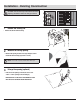
Installation - Existing Construction CAUTION: Turn off electricity at the breaker box before beginning installation. Review all safety precautions. 1 Remove the existing fan Remove the old fan from the ceiling. 2 Measure the ceiling opening easure the opening to assure it is large enough to accomM modate the new fan body (A) (7.50 in. x 7.25 in.). NOTE: 7.25 inch side of opening should be flush with the joist.
Installation - Existing Construction (continued) 4 Remove the fan motor assembly emove the three screws (1) that hold the fan motor assembly R in place. Remove the fan motor assembly from the fan housing. Unplug the fan power unit. 1 5 6 Remove the wiring box knockout Remove the wiring box cover from the fan housing. Remove the wiring knockout from the wiring box cover with a flathead screwdriver (not included).
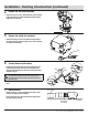
Installation - Existing Construction (continued) 8 Insert the fan housing Insert the fan housing through the existing hole in the ceiling. The fan housing should be level and perpendicular to the joist or stud. 9 Mount the fan housing to the joist Joist or wall stud Mount the fan housing to the joist or stud using nails (not included) where indicated by arrows inside the fan housing. 10 Reattach the motor assembly Plug the motor assembly back into the power unit.
Humidity Sensor Operation 1 Humidity sensing mode Move the wall on/off switch to the “ON” position. The LED indicator light in the fan is BLUE. The fan will automatically go on when the humidity level in the room goes above 60%. BLUE LED LIGHT 2 Full speed mode Cycle the wall on/off switch to the “OFF” position, then back to the “ON” position. The LED indicator light in the fan is AMBER. AMBER LED LIGHT 3 Fan off Move the wall on/off switch to the “OFF” position.
Troubleshooting Problem The fan seems louder than it should. Possible Cause Solution The CFM is too great. Be sure the CFM rating on the fan matches the square footage of your room. The damper is damaged or not working properly. Check the damper to ensure it is opening and closing properly. If the damper has become damaged, please call Customer Service. The bend in the duct is too close to the fan discharge. Be sure you do not have any sharp bends in the duct closer than 18 in.
Questions, problems, missing parts? Before returning to the store, call Hampton Bay Customer Service 8 a.m. - 7 p.m., EST, Monday-Friday, 9 a.m. - 6 p.m., EST, Saturday 1-855-HD-HAMPTON HAMPTONBAY.COM Retain this manual for future use.