Item #1001-419-055 Model #7134-01 USE AND CARE GUIDE NO CUT HUMIDITY SENSING VENTILATION FAN Questions, problems, missing parts? Before returning to the store, call Hampton Bay Customer Service 8 a.m. - 7 p.m., EST, Monday-Friday, 9 a.m. - 6 p.m., EST, Saturday 1-855-HD-HAMPTON HAMPTONBAY.COM THANK YOU We appreciate the trust and confidence you have placed in Hampton Bay through the purchase of this ventilating bath fan. We strive to continually create quality products designed to enhance your home.
Table of Contents Table of Contents............................................................ 2 Safety Information........................................................... 2 Product Specifications.................................................... 3 Typical Installation........................................................... 3 Wiring Diagram................................................................ 3 Quick connector instructions.................................................... 3 Warranty...
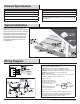
Product Specification SPECIFICATIONS SPECIFICATIONS Airflow: 80 CFM Power consumption: 12 W 120 V, 60 Hz Weight: 4.00 lbs. Duct diameter: 4 in. Ceiling Opening Dimension Requirements: 7-1/2 in. (L) x 7-1/4 in. (W) x 5-3/4 in. (H) Sound output: 1.5 Sones Typical Installation The ducting from this fan to the outside of the building has a strong effect on the air flow, noise and energy use of the fan.
Warranty LIMITED LIFETIME WARRANTY WHAT IS COVERED If this product fails due to a defect in materials or workmanship at any time during the first FIVE years of ownership, the manufacturer will replace it free of charge, postage-paid at their option. This warranty does not cover products that have been abused, altered, damaged, misused, cut or worn. This warranty does not cover use in commercial applications. Use only manufacturer-supplied genuine warranty repair replacement parts to repair this fan.
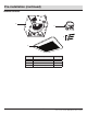
Pre-installation (continued) PACKAGE CONTENTS A C D B Part Description Quantity A B C D Fan body Grille Duct connector Long wood screws (ø4x25mm) 1 1 1 3 5 HAMPTONBAY.COM Please contact 1-855-HD-HAMPTON for further assistance.
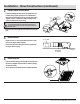
Installation - New Construction CAUTION: Make sure power is switched off at service panel before starting installation. NOTE: Ceiling mount only. 1 2 3 Remove the wiring box knockout Remove the wiring box cover from the fan housing. Remove the wiring knockout from the wiring box cover with a flathead screwdriver (not included). Joist or wall stud Fan housing placement Place the fan housing next to a ceiling joist or wall stud.
Installation - New Construction (continued) 4 Connect house and fan wires Pull the wire through the hole and into the junction box (not included). Using a quick connector, secure 120 VAC house wiring from the wall switch to the fan as shown in the wiring diagram on page 3. 14AWG is the smallest conductor that shall be used for branch-circuit wiring.
Installation - Existing Construction CAUTION: Turn off electricity at the breaker box before beginning installation. Review all safety precautions. 1 Remove the existing fan Remove the old fan from the ceiling. 2 Measure the ceiling opening easure the opening to assure it is large enough to accomM modate the new fan body (A) (7.50 in. x 7.25 in.). NOTE: 7.25 inch side of opening should be flush with the joist.
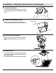
Installation - Existing Construction (continued) 4 Remove the fan motor assembly emove the three screws (1) that hold the fan motor assembly R in place. Remove the fan motor assembly from the fan housing. Unplug the fan power unit. 1 5 6 Remove the wiring box knockout Remove the wiring box cover from the fan housing. Remove the wiring knockout from the wiring box cover with a flathead screwdriver (not included).
Installation - Existing Construction (continued) 8 Insert the fan housing Insert the fan housing through the existing hole in the ceiling. The fan housing should be level and perpendicular to the joist or stud. 9 Mount the fan housing to the joist 10 Ceiling joist Mount the fan housing to the joist using three long wood screws (D) where indicated by arrows inside the fan housing. Reattach the motor assembly Plug the motor assembly back into the power unit.
Humidity Sensor Operation 1 Humidity sensing mode Move the wall on/off switch to the “ON” position. The LED indicator light in the fan is BLUE. The fan will automatically go on when the humidity level in the room goes above 60%. BLUE LED LIGHT 2 Full speed mode Cycle the wall on/off switch to the “OFF” position, then back to the “ON” position. The LED indicator light in the fan is AMBER. AMBER LED LIGHT 3 Fan off Move the wall on/off switch to the “OFF” position.
Troubleshooting Problem The fan seems louder than it should. Possible Cause Solution The CFM is too great. Be sure the CFM rating on the fan matches the square footage of your room. The damper is damaged or not working properly. Check the damper to ensure it is opening and closing properly. If the damper has become damaged, please call Customer Service. The bend in the duct is too close to the fan discharge. Be sure you do not have any sharp bends in the duct closer than 18 in.
Questions, problems, missing parts? Before returning to the store, call Hampton Bay Customer Service 8 a.m. - 7 p.m., EST, Monday-Friday, 9 a.m. - 6 p.m., EST, Saturday 1-855-HD-HAMPTON HAMPTONBAY.COM Retain this manual for future use.
Artículo #1001-419-055 Modelo #7134-01 GUÍA DE USO Y CUIDADO VENTILADOR CON SENSOR DE HUMEDAD SIN CORTES ¿Preguntas, problemas, piezas faltantes? Antes de volver a la tienda, llame a la sección de Servicio al cliente de Hampton Bay de 8 a.m a 7 p.m., hora estándar del Este de lunes a viernes y los sábados de 9 a.m. a 6 p.m., hora estándar del Este. 1-855-HD-HAMPTON HAMPTONBAY.COM GRACIAS Le agradecemos por depositar su confianza en Hampton Bay con la compra de este ventilador para baño.
Índice Índice................................................................................ 2 Información de seguridad.............................................. 2 Especificaciones del producto....................................... 3 Instalación común........................................................... 3 Diagrama del cableado................................................... 3 Instrucciones para el conector de conexión rápida................... 3 Garantía.......................................
Especificaciones del Producto Flujo de aire: 80 CFM SPECIFICATIONS SPECIFICATIONS Consumo de energía 12.0 vatios 120 V, 60 Hz Peso: 4.00 lb Diámetro del conducto: 10,16 cm Dimensiones requeridas para la apertura del techo: 19,05 cm A x 18,41 cm L x 5-3/4 in. (H) x 14.6 cm de alto Potencia de sonido: Potencia del sonido: 1,5 sonios Instalación Común El conducto que va desde el ventilador hasta el exterior tiene un gran efecto en el flujo de aire, ruido y consumo de energía del ventilador.
Garantía GARANTÍA LIMITADA DE POR VIDA ¿QUÉ ESTÁ CUBIERTO Si este producto falla debido a un defecto en el material o la mano de obra en cualquier momento durante los primeros CINCO años de poseerlo, el fabricante lo reemplazará sin cargos y con el franqueo pagado a su discreción. Esta garantía no cubre productos que hayan sufrido abusos, modificaciones, daños, uso indebido, cortes o desgaste. Esta garantía no cubre el uso con fines comerciales.
Antes de la Instalación CONTENIDO DEL PAQUETE A C D B Parte Descripción Cantidad A B C Cuerpo del ventilador Rejilla Conector de conducto Tornillos de madera largos (ø4x25mm) 1 1 1 D 18 3 HAMPTONBAY.COM Por favor, póngase en contacto con 1-855-HD-HAMPTON para obtener más ayuda.
Instalación en Construcciones Nuevas PRECAUCIÓN: Asegúrese de que la alimentación esté desconectada en el panel de servicio antes de comenzar la instalación. NOTA: Soporte de techo única 1 2 Retire la cubierta de la caja del cableado. Retire la cubierta de la caja del cableado (2.1) de la carcasa del ventilador (A). Retire el orificio ciego del cableado de la cubierta de la caja del cableado con un destornillador de cabeza plana (no incluido).
Instalación en Construcciones Nuevas (continuado) 4 Conecte los cables de la casa y del ventilador Jale el conductor a través del orificio y en la caja de unión (no incluida). Usando un conector rápido, asegure el conductor de la casa de 120 VCA desde el interruptor de la pared al ventilador como se muestra en el diagrama de cableado de la página 3.El conductor de 14 AWG es el más pequeño que se usará para el cableado del circuito de derivación.
Instalación en construcciones existente PRECAUCIÓN: Desconecte la electricidad en la caja del interruptor de circuito antes de comenzar la instalación. Revise todas las precauciones de seguridad. 1 Retire el ventilador existente Retire el ventilador antiguo del techo. 2 Mida la abertura del techo M ida la abertura para asegurarse de que es lo suficientemente grande como para ubicar el nuevo cuerpo del ventilador (A) (19,05 cm x 18,41 cm).
Instalación en construcciones existente (continuado) 4 Retire el ensamble del motor del ventilador R etire los tres tornillos (1) que sostienen el ensamble del motor del ventilador en su lugar. Retire el ensamble del motor del ventilador de la carcasa del ventilador. Desenchufe la unidad de tomacorriente del ventilador. 1 5 6 Retire la cubierta de la caja del cableado. Retire la cubierta de la caja del cableado (2.1) de la carcasa del ventilador (A).
Instalación en construcciones existente (continuado) 8 Inserte la carcasa del ventilador Inserte la carcasa del ventilador a través del orificio existente en el techo. La carcasa del ventilador debe estar al nivel de la vigueta o del montante y ser perpendicular a estos. 9 Montaje de la carcasa del ventilador Vigueta del techo M ontar la carcasa del ventilador en la vigueta con tres tornillos de madera largos (D) donde se indican mediante flechas dentro de la carcasa del ventilador.
Funcionamiento del sensor de humedad 1 Modo del sensor de humedad Mueva el interruptor de encendido y apagado en la pared a la posición “ON”. La luz LED indicadora del ventilador es AZUL. El ventilador se encenderá automáticamente cuando el nivel de humedad en la habitación sea superior al 60%. Luz LED azul 2 Modo de máxima velocidad Mueva el interruptor de encendido y apagado del control de pared a la posición OFF, luego vuelva a la posición ON. La luz LED indicadora del ventilador es ÁMBAR.
Solución De Problemas Problema El ventilador hace más ruido de lo que debería. El ventilador no ventila la habitación. Causa Posible Solución Os m3/min son demasiados. Asegúrese de que la clasificación de m3/min en el ventilador coincida con los metros cuadrados de su habitación. El regulador de tiro no funciona en forma adecuada o está dañado. Revise el regulador de tiro para garantizar que se abra y cierre correctamente. Si el regulador de tiro se ha dañado, llame al Servicio al Cliente.
¿Preguntas, problemas, piezas faltantes? Antes de volver a la tienda, llame a la sección de Servicio al cliente de Hampton Bay de 8 a.m a 7 p.m., hora estándar del Este de lunes a viernes y los sábados de 9 a.m. a 6 p.m., hora estándar del Este. 1-855-HD-HAMPTON HAMPTONBAY.COM Conserve este manual para uso futuro.