Item #1002-368-503 Model #7136-01 USE AND CARE GUIDE HUMIDITY SENSING VENTILATION FAN Questions, problems, missing parts? Before returning to the store, call Hampton Bay Customer Service 8 a.m. - 7 p.m., EST, Monday-Friday, 9 a.m. - 6 p.m., EST, Saturday 1-855-HD-HAMPTON HAMPTONBAY.COM THANK YOU We appreciate the trust and confidence you have placed in Hampton Bay through the purchase of this ventilating bath fan. We strive to continually create quality products designed to enhance your home.
Table of Contents Table of Contents............................................................ 2 Safety Information........................................................... 2 Product Specifications.................................................... 3 Typical Installation........................................................... 3 Wiring Diagram................................................................ 3 Quick connector instructions.................................................... 3 Warranty...
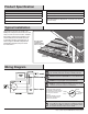
Product Specification SPECIFICATIONS SPECIFICATIONS Airflow: 140 CFM Power consumption: 48 W 120 V, 60 Hz Weight: 10.78 lbs. Duct diameter: 6 in. Ceiling Opening Dimension Requirements: 10-13/16 in. (L) x 10-1/2 in. (W) x 8-1/2 in. (H) Sound output: 1.0 Sones Typical Installation The ducting from this fan to the outside of the building has a strong effect on the air flow, noise and energy use of the fan.
Warranty LIMITED LIFETIME WARRANTY WHAT IS COVERED If this product fails due to a defect in materials or workmanship at any time during the first FIVE years of ownership, the manufacturer will replace it free of charge, postage-paid at their option. This warranty does not cover products that have been abused, altered, damaged, misused, cut or worn. This warranty does not cover use in commercial applications. Use only manufacturer-supplied genuine warranty repair replacement parts to repair this fan.
Pre-installation (continued) PACKAGE CONTENTS C D E A F G B H Part Description Quantity A B C D E F G H Fan housing Grille Long wood screws (M4x30mm) Machine screw (M4x12mm) Short machine screw (M4x10mm) Suspension bracket I Suspension bracket II Suspension bracket III 1 1 8 2 1 1 1 1 5 HAMPTONBAY.COM Please contact 1-855-HD-HAMPTON for further assistance.
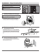
Installation - New Construction CAUTION: Make sure power is switched off at service panel before starting installation. NOTE: Ceiling mount only. 1 Attaching fan housing to the ceiling joist A CAUTION: Allow for the thickness of ceiling board used in your application. Do not flush mount to joist. Flange should be flush with the ceiling board. If spacing between joists is 12 in. apart, use 4 long wood screws (C) to attach the fan housing (A) to the ceiling joist 0.
Installation - New Construction (continued) 4 5 Securing suspensions brackets onto fan housing Secure suspension brackets (G, H) to the fan housing (A) using the two machine screws (D) and secure suspension bracket (F) to the other side of housing using the short machine screw (E). Remove the wiring cover. Pull the house wires through the wire box cover hole (5.1). Using the quick connector, secure 120 V AC house wiring from the wall switch to the fan as shown in the wiring diagram on page 3.
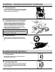
Installation - Existing Construction 1 Remove the existing fan CAUTION: Allow for the thickness of ceiling board used in your application. Do not flush mount to joist. Flange should be flush with the ceiling board. 1 11 easure the opening to ensure it is large enough to M accommodate the new fan body (A) (10.25 in. x 10.25 in.). 10 4 5 6 7 Measure the ceiling opening 9 2 0.24" Remove the old fan from the ceiling. 8 3 Enlarge the opening (optional) " 10.
Installation - Existing Construction (continued) 2 A Attaching fan housing to the ceiling joist CAUTION: Allow for the thickness of ceiling board used in your application. Do not flush mount to the joist. Flange should be flush with the ceiling board. If spacing between joists is 12 in. apart, use 4 long wood screws (C) to attach the fan housing (A) to the ceiling joist 0.
Installation - Existing Construction (continued) 7 Connecting the duct 8 Removing wiring cover on the fan housing Connect a 6 in. circular duct (not supplied) and vent to the outside. Secure it with duct tape (not supplied) or clamp (not supplied) to make the connection secure and air tight. Remove the wiring cover. Pull the house wires through the wire box cover hole (8.1).
Humidity Sensing Operation (continued) 3 Fan off Move the wall on/off switch to the “OFF” position. Care and Maintenance WARNING: Disconnect power supply before servicing. See SAFETY INFORMATION before proceeding. Routine maintenance should be done at least once a year. Never use solvents, thinner or harsh chemicals for cleaning the fan. Do not allow water to enter the motor. Do not immerse metal parts in water. Troubleshooting Problem The fan seems louder than it should.
Questions, problems, missing parts? Before returning to the store, call Hampton Bay Customer Service 8 a.m. - 7 p.m., EST, Monday-Friday, 9 a.m. - 6 p.m., EST, Saturday 1-855-HD-HAMPTON HAMPTONBAY.COM Retain this manual for future use.
Núm. de artículo1002-368-503 Núm. de modelo 7136-01 GUÍA DE USO Y CUIDADO SISTEMA DE VENTILACIÓN DETECTOR DE HUMEDAD ¿Tiene preguntas, problemas, o faltan piezas? Antes de regresar a la tienda, llame a Servicio al Cliente de Hampton Bay de lunes a viernes de 8 a.m. a 7 p.m., sábado de 9 a.m. a 6 p.m., hora local del Este. 1-855-HD-HAMPTON HAMPTONBAY.COM GRACIAS Apreciamos la confianza que ha depositado en Hampton Bay por la compra de este sistema de ventilación de baño.
Índice Índice................................................................................ 2 Información de seguridad.............................................. 2 Especificaciones del producto....................................... 3 Instalación típica............................................................. 3 Diagrama de cableado.................................................... 3 Instrucciones del conector rápido............................................ 3 Garantía...........................
Especificaciones del producto ESPECIFICACIONES Flujo de aire: 140 pies3/min (CFM) ESPECIFICACIONES Consumo de energía: 48 W 120 V, 60 Hz Peso: 10.78 lbs. Diámetro del ducto: 6 pulg. Requerimientos de dimensión de abertura del techo: 10-13/16 pulg. (L) x 10-1/2 pulg. (Ancho) x 8-1/2 pulg. (Alto) Salida de sonido: 1.0 Sones Instalación típica El ducto de este ventilador al exterior del edificio tiene un fuerte efecto en el flujo del aire, ruido y uso de la energía del ventilador.
Garantía GARANTÍA DE POR VIDA LIMITADA LO QUE ESTÁ CUBIERTO Si este producto falla debido a un defecto en materiales o mano de obra en cualquier momento durante los primeros CINCO años de propiedad, el fabricante lo reemplazará libre de cargos. Esta garantía no cubre productos que han sido maltratados, alterados, dañados, mal empleados, cortados o deteriorados. Esta garantía no cubre el uso en aplicaciones comerciales.
Pre-instalación (continuación) CONTENIDO DEL PAQUETE C D E A F G B H Pieza Descripción Cantidad A B C D E F G H Carcasa del ventilador Rejilla Tornillos largos para madera (M4x30mm) Tornillos de máquina (M4x12mm) Corto tornillos de máquina (M4x10mm) Soporte de suspensión I Soporte de suspensión II Soporte de suspensión III 1 1 8 2 1 1 1 1 5 HAMPTONBAY.COM Póngase en contacto con el 1-855-HD-HAMPTON para asistencia adicional.
Instalación: construcción nueva PRECAUCIÓN: Asegúrese de que la energía esté desconectada en el panel de servicio antes de comenzar la instalación. NOTA: Montaje en techo únicamente. 1 Instalación de la carcasa del ventilador en la viga del techo A PRECAUCIÓN: Tenga en cuenta el espesor de la tabla del techo utilizada en su aplicación. No monte al ras en la viga. La brida debe estar al ras con la tabla del techo. Si el espacio de separación entre las vigas es de 12 pulg.
Instalación: construcción nueva (continuación) 4 Cómo asegurar los soportes de suspensión sobre la carcasa del ventilador F Asegure los soportes de suspensión (G, H) a la carcasa del a (A) con los dos tornillos de la máquina (D) y asegure el soporte de la suspensión (F) al otro lado de la carcasa utilizando el cortocircuito tornillo de la máquina (E). D E G, H 5 Extracción de la cubierta del cableado sobre la carcasa del ventilador. Retire la cubierta del cableado.
Instalación: construcción existente 1 Retire el ventilador existente. PRECAUCIÓN: Tenga en cuenta el espesor de la tabla del techo utilizada en su aplicación. No monte al ras en la viga. La brida debe estar al ras con la tabla del techo. 11 1 Mida la abertura del techo ida la abertura para asegurarse de que sea suficientemente M larga para que se acomode al cuerpo del ventilador nuevo (A) (10.25 pulg. x 10.25 pulg.). 10 7 4 5 6 Tabla del techo 9 2 0.24 Retire el ventilador viejo del techo.
Instalación: construcción existente (continuación) 2 A Instalación de la carcasa del ventilador en la viga del techo PRECAUCIÓN: Tenga en cuenta el espesor de la tabla del techo utilizada en su aplicación. No monte al ras en la viga. La brida debe estar al ras con la tabla del techo. Viga Si el espacio de separación entre las vigas es de 12 pulg., use 4 tornillos para madera largos (C) para instalar la carcasa del ventilador (A) en la viga del techo 0.
Instalación: construcción existente (continuación) 7 Conexión del ducto 8 Extracción de la cubierta del cableado sobre la carcasa del ventilador. Conecte un ducto circular de 6 pulg. (no suministrado) y ventile al exterior. Asegúrelo con cinta de ducto (no suministrada) o una abrazadera (no suministrada) para que la conexión sea segura y a prueba de aire. Retire la cubierta del cableado. Hale los cables de la casa a través del agujero de la cubierta de la caja de cables (8.1).
Operación del sensor de humedad (continuación) 3 Ventilador apagado Mueva el interruptor de pared "on/off" en la posición “OFF”. Cuidado y mantenimiento ADVERTENCIA: Desconecte la fuente de alimentación antes de dar servicio. Consulte INFORMACIÓN DE SEGURIDAD antes de proceder. Se debe hacer mantenimiento de rutina al menos una vez al año. Nunca use solventes, diluyentes o productos químicos fuertes para limpiar el ventilador. No permita que entre agua al motor.
¿Tiene preguntas, problemas, o faltan piezas? Antes de regresar a la tienda, llame a Servicio al Cliente de Hampton Bay de lunes a viernes de 8 a.m. a 7 p.m., sábado de 9 a.m. a 6 p.m., hora local del Este. 1-855-HD-HAMPTON HAMPTONBAY.COM Conserve este manual para uso futuro.