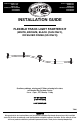
US Item #1000000-922 1000000-948 1000000-924 US Model #847658004017 847658004048 847658004031 CAN Item #1000777-349 1000777-350 1000776-346 CAN Model #847658004055 847658004062 847658004024 INSTALLATION GUIDE FLEXIBLE TRACK LIGHT STARTER KIT (WHITE, BRONZE, BLACK (CAN ONLY), OR SILVER FINISH (US ONLY)) Questions, problems, missing parts? Before returning to the store, call Hampton Bay Customer Service 8 a.m. - 6 p.m., EST, Monday - Friday 855-HD-HAMPTON (1-855-434-2678) HAMPTONBAY.
Table of Contents Hardware Included ..................................... 3 Package Contents ...................................... 4 Installation ............................................. 5 Table of Contents ..................................2 Safety Information .................................2 Warranty .................................................2 Pre-Installation ......................................3 Planning Installation................................... 3 Tools Required .................
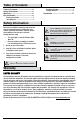
Pre-Installation PLANNING INSTALLATION Before you begin installation, check to ensure all parts listed in the Hardware Included and Package Contents section are contained within the packaging and that there is no damage to any of the parts. TOOLS REQUIRED Phillips screwdriver Power drill HARDWARE INCLUDED NOTE: Hardware not shown to actual size.
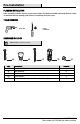
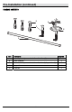
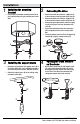
Pre-Installation (continued) PACKAGE CONTENTS D A C B E Part Description Quantity A Mounting Bracket (preassembled to Power Feed Stem (B)) 1 B Power Feed Stem 1 C Decorative Collar (preassembled to Power Feed Stem (B)/Support Stem (D)) 5 D Support Stem 4 E Track Rail 1 4
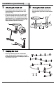
Installation 1 Installing the mounting bracket 2 □ Install the preassembled mounting bracket (A) to the junction box by using the junction box screws (AA). Connecting the wires □ Connect the white wire from the supply circuit to the white wire from the power feed stem (B). □ Connect the black wire from the supply circuit to the black wire from the power feed stem (B). □ Connect the green ground wire from the supply circuit to the green wire from the power feed stem (B).
Installation (continued) 5 6 Attaching the track rail Closing the track contacts □ Close the connector tight and rethread the decorative collar (C) to lock the track contacts closed. □ Ensure that the ground side of the track rail (E) (exposed copper wire on top of the track rail) is facing the ceiling.
Questions, problems, missing parts? Before returning to the store, call Hampton Bay Customer Service 8 a.m.- 6 p.m., EST, Monday-Friday 855-HD-HAMPTON (1-855-434-2678) HAMPTONBAY.COM Retain this manual for future use.
Núm. de artículo Canadá 1000777-349 1000777-350 1000776-346 Núm. de modelo Canadá 847658004055 847658004062 847658004024 Núm. de artículo EE. UU. 1000000-922 1000000-948 1000000-924 Núm. de modelo EE. UU. 847658004017 847658004048 847658004031 GUÍA DE INSTALACIÓN JUEGO DE INTERRUPTOR DE ENCENDIDO DE LÁMPARA DE RIEL FLEXIBLE (ACABADO BLANCO, BRONCE, NEGRO (SOLAMENTE CANADÁ), O ACABADO PLATA (SOLAMENTE EE. UU.
Tabla de contenido Herraje incluido.................................................... 3 Contenido del paquete ......................................... 4 Instalación ...................................................... 5 Tabla de contenido ........................................ 2 Información de seguridad ............................. 2 Garantía .......................................................... 2 Pre-instalación ...............................................
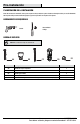
Pre-instalación PLANIFICACIÓN DE LA INSTALACIÓN Antes de comenzar la instalación, revise para asegurarse de que todas las piezas listadas en Herraje Incluido y la sección Contenido del Paquete estén presentes dentro del paquete y que no hayan daños en ninguna de las piezas. HERRAMIENTAS REQUERIDAS Destornillador Phillips Taladro HERRAJE INCLUIDO NOTA: No se muestra el herraje en el tamaño real.
Pre-instalación (continuación) CONTENIDO DEL PAQUETE D A C B E Pieza Descripción Cantidad A Soporte de montaje (preensamblado al Vástago de alimentación de energía (B)) 1 B Vástago de alimentación de energía 1 C Collarín decorativo (preensamblado al Vástago de alimentación de energía (B)/Vástago de soporte (D)) 5 D Vástago de soporte 4 E Riel de pista 1 4
Instalación 1 □ Instalación del soporte de montaje Instale el soporte de montaje preensamblado (A) en la caja de empalmes usando los tornillos de la caja de empalmes (AA). 2 Conexión de los cables □ □ □ □ □ Conecte el cable blanco del cirtuito de alimentación al cable blanco del vástago de alimentación de energía (B). Conecte el cable negro del cirtuito de alimentación al cable negro del vástago de alimentación de energía (B).
Instalación (continuación) 5 □ □ 6 Instalación del riel de pista Asegúrese de que el lado de tierra del riel de pista (E) (cable de cobre expuesto en la parte superior del riel de pista) esté mirando al techo.
¿Tiene preguntas, problemas, o faltan piezas? Antes de regresar a la tienda, llame a Servicio al Cliente de Hampton Bay de lunes a viernes de 8 a.m. y 6 p.m., hora local del Este 855-HD-HAMPTON (1-855-434-2678) HAMPTONBAY.COM Conserve este manual para uso futuro.