326 254/78639/23DE9447-PB84 XXX XXX/80427/23DE9447-PC72 XXX XXX/82902/23DE9447-PM83 XXX XXX/82605/23DE9447-PT85 USE AND CARE GUIDE CHARLES MILL ELECTRIC FIREPLACE Questions, problems, missing parts? Before returning to the store call Hampton Bay Customer Service 8 a.m. - 6 p.m., EST, Monday-Friday 1-877-527-0313 HAMPTONBAY.COM THANK YOU We appreciate the trust and confidence you have placed in Hampton Bay through the purchase of this electric fireplace.
Table of Contents Maximum Load Warning............................................ 2 Safety Information...................................................... 3 Warranty...................................................................... 4 Pre-Assembly.............................................................. 5 Hardware Included ................................................... 5 Product Specifications........................................................ 5 Tools Required...........................
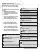
Safety Information Please read and understand this entire manual before attempting to assemble, operate or install the product. If you have any question regarding the product, please call customer service at 1-877-5270313, 8 a.m.-6 p.m., EST, Monday-Friday. WARNING: This appliance is not a toy. Supervise children When using electrical appliances, always follow basic precautions to reduce the risk of fire, electrical shock, and injury to persons including the following: playing near it. 1.
Warranty 1 Year Limited Warranty: The manufacturer warrants this product to be free from manufacturing and material defects for a period of one year from date of purchase, subject to the following conditions and limitations: 1. Install and operate this Electric Fireplace in accordance with the installation and operating instructions furnished with the product at all times. Any unauthorized repair, alteration, willful abuse, accident, or misuse of the product shall nullify this warranty. 2.
Pre-Assembly HARDWARE INCLUDED AA BB CC EE DD FF GG H-2 H-1 HH Part AA BB CC DD EE FF GG HH II JJ KK LL MM II JJ KK Description Bolt Long Flathead Screw Wood Dowel Shelf Pin Screw with Washer Head Knob (with bolt, not to scale) Short Flathead Screw Euro Hinge (not to scale) Connection Plate (pre-attached) Plastic 2 Hole Connector Block (pre-attached) Plastic 3 Hole Connector Block (pre-attached) Floor Glide (pre-attached) Touch-up Pen Model LL MM Part Number PH-BLTBLK001 N/A PH-DWLNTL001 N/
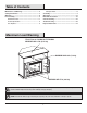
Pre-Assembly (continued) PACKAGE CONTENTS P NOTE: All panels are labeled left and right as viewed from the front of the unit.
Assembly 1 2 Assembling the center panel Locate the Center Left Side Panel (B), Center Right Side Panel (C), Center Shelf (D), and set out face down on a scratch-free surface. Insert Bolts (AA) through the holes in the Plastic Connector (KK) and tighten. Assembling the front panel Locate the Left Front Panel (I), Right Front Panel (J), Center Front Panel (R), and set out face down on a scratch-free surface. Insert one Wood Dowel (CC) into each of the pre-drilled holes.
Assembly (continued) 3 4 Installing the center shelf Attach the completed assembly from step 1 to the completed assembly from step 2. Insert Bolts (AA) through the holes in the Plastic Connector (KK) and tighten. Installing the hinges to the panels Attach the Euro Hinge (H-1) to the Right Side Panel (F). Use a Phillips head screwdriver to tighten the Short Flathead Screw (GG) through the pre-drilled holes. Repeat for the Left Side Panel (E).
Assembly (continued) 6 7 Installing the side panel Attach the Left Side Panel (E) to the Center Shelf (D), using Bolts (AA) through the holes in the Plastic Connector (KK) and tighten. Repeat for the Right Side Panel (F). Insert Wood Dowels (CC) into the holes in the Hearth/Base (A). Push the Base (A) snug to the completed assembly from step 6 as shown in the diagram. Use a Phillips head screwdriver to tighten the Long Flathead Screws (BB) through the pre-drilled holes in the Hearth/Base (A).
Assembly (continued) 9 10 Installing the back panel Installing the mantel top Locate the Mantel/Top (G) and lay the finished side up on top of the completed assembly. From the inside, attach the Mantel/Top (G) using Bolts (AA) through the pre-drilled holes in the Plastic Connector (KK). Hand tighten only. AA Attach the Side Back Panel (K) and the Center Back Panel (Q) to the back of the completed assembly from step 9.
Assembly (continued) 12 Installing the wood shelves Choose the desired height for the Shelf (H) and place the four Shelf Pins (DD) into the same height shelf holes inside the side panels. Insert the Wood Shelf (H), and allow the Wood Shelf (H) to rest on the Shelf Pin (DD). H DD 13 Inserting the fireplace into the mantel assembly Install Insert From Back Lift the fireplace insert carefully into the back of the unit and center in the insert opening.
Assembly (continued) 14 Installing the L corner brace Locate the L Corner Brace (O) and Top Corner Extension (P) and set out face down on a scratch-free surface. Insert Bolts (AA) through the holes in the Plastic Connector (JJ) and tighten. AA O JJ P 15 Installing the top corner extension CC Attach the completed assembly from step 14 into place at the back of the mantel. Insert Wood Dowel (CC) into the holes in the back of the Top Mantel (G).
Operation NOTE: The control panel can be accessed at the upper-right corner of the insert. When a function is changed °C °F from the control panel or remote control there will be a corresponding indicator (see Figure 1) on the upper-right of the projection screen. The indicator shows the function changed and the level selected by the control panel or remote control. When the function is turned off, the corresponding indicator will flash several times and then fade off. Fig .
Operation 5 Replacing the remote control battery 6 Disposing of used batteries When the remote control stops operating or its range seems reduced, it is time to replace the battery with new ones. On the back end of the remote, press and slide the battery door open and remove the old battery. Insert 2 AAA batteries, checking that the + and sides of the battery match inside the battery com partment. Replace the battery compartment door.
FCC/ICC Information This equipment has been tested and found to comply with the limits for Class B digital device, pursuant to part 15 of the FCC Rules. These limits are designed to provide reasonable protection against harmful interference in a residential installation.
Troubleshooting PROBLEM POSSIBLE CAUSE CORRECTIVE ACTION There is no power and the logs do not glow. There is no power to the unit. Check that the unit is plugged into a standard 120V outlet. Press the Power button several times, make sure power is set to the “ON”position. The logs glow but there is no flame effect. The flame effect turned off. Press the Flame button several times. This is normal operation. Check your heater cord and plug connections.
Replacement Parts For replacement parts, call our customer service department at 1-877-527-0313, 8 a.m.-6 p.m., EST, Monday-Friday. Description Part No. 23EF023GRA Qty.
Questions, problems, missing parts? Before returning to the store call Hampton Bay Customer Service 8 a.m. - 6 p.m., EST, Monday-Friday 1-877-527-0313 HAMPTONBAY.COM RETAIN THIS MANUAL FOR FUTURE USE.
326 254/78639/23DE9447-PB84 XXX XXX/80427/23DE9447-PC72 XXX XXX/82902/23DE9447-PM83 XXX XXX/82605/23DE9447-PT85 GUÍA DE USO Y MANTENIMIENTO CHARLES MILL CHIMENEA ELÉCTRICA ¿Preguntas, problemas o piezas faltantes? Antes de regresar a la tienda, llama al al Servicio al Cliente de Hampton Bay de Lunes a Viernes entre 8 a.m. y 6 p.m., (hora del Este de EE. UU.) 1-877-527-0313 HAMPTONBAY.COM GRACIAS POR TU COMPRA. Apreciamos la confianza que has depositado en Hampton Bay al comprar esta chimenea eléctrica.
Índice Advertencia sobre la Capacidad de Carga Máxima....................................... 2 Información de Seguridad......................................... 3 Garantía....................................................................... 4 Pre-Instalación........................................................... 5 Herrajes ............................................................................. 5 Especificaciones del Producto............................................ 5 Herramientas Necesarias..
Información de Seguridad Lee y entiende este manual por completo antes de intentar ensamblar, operar o instalar el producto. Si tienes alguna pregunta referente al producto, por favor comunícate con el Servicio al Cliente de Hampton Bay al 1-877-527-0313, de 8 a.m. a 6 p.m., hora del Este de EE. UU., de lunes a viernes. ADVERTENCIA: Este electrodoméstico no es un juguete. Supervisa a los niños que estén jugando cerca del mismo.
Garantía Garantía Limitada de 1 Año: El fabricante garantiza que este producto no presentará defectos de fabricación o materiales durante un año a partir de la fecha de compra, sujeto a las siguientes condiciones y limitaciones. 1. Instale y opere esta Chimenea Eléctrica en todo momento de acuerdo con las instrucciones de instalación y funcionamiento incluidas con el producto. Cualquier reparación no autorizada, modificación, abuso intencional, accidente o uso incorrecto del producto anulará esta garantía.
Pre-Instalación HERRAJES AA BB CC EE DD FF GG H-2 H-1 HH Pieza AA BB CC DD EE FF GG HH II JJ KK LL MM II JJ KK Descripción Perno Largo Tornillo de cabeza plana Clavija de Madera Pasador de Estante Tornillo Perilla (con perno, no se muestra a escala) Corto Tornillo de cabeza plana Bisagra Euro (no se muestra a escala) Placa de Conexión (pre-instalada, no se muestra a escala) Plastic Conector 2 Block Hole (no se muestra a escala) Plastic Conector 3 Block Hole (no se muestra a escala) Piso Glide
Pre-Instalación (continuación) Contenido del Paquete NOTA: Todos los paneles se han P establecido como izquierdo y derecho viéndolos desde la parte frontal de la unidad.
Ensamblaje 1 2 Instalación del panel central Ubica el Panel Central Izquierdo (B), Panel Central Derecho (C), el Estante Central (D) y colócalos boca abajo sobre una superficie no abrasiva. Coloca los Pernos (AA) a través de los orificios pretaladrados en el Conector Plástico y apriétalos. Instalación del panel frontal Ubica el Panel Frontal Izquierdo (I), el Panel Frontal Derecho (J), el Panel Central Frontal (R) y colócalos boca abajo sobre una superficie no abrasiva.
Ensamblaje (continuación) 3 4 Instalación del estante central Instala el ensamblaje terminado del paso 2 en el ensamblaje terminado del paso 1. Coloca los Pernos (AA) a través de los orificios pretaladrados en el Conector Plástico (KK) y apriétalos. Instalación de la bisagra Instala la Bisagra Euro (H-1) en el Panel Lateral Derecho (F). Usa un destornillador Phillips para apretar el Tornillo para Madera (GG) a través de los orificios pretaladrados. Repite el paso para el lado contrario (E).
Ensamblaje (continuación) 6 7 Instalación del Panel Lateral Sujeta el Panel Central Izquierdo (E) al Estante Central (D), usando los Pernos (AA) a través de los orificios pretaladrados en el Conector Plástico (KK) y apriétalos. Repite el paso para el lado contrario (F). AA Instalación de la base Coloca una Clavija de Maderas (CC) en los orificios en la Chimenea/Base (A). Empuja el ensamblaje (A) terminado del paso 6 firmemente contra la chimenea/base como se muestra en el diagrama.
Ensamblaje (continuación) 9 10 Instalación del Panel Posterior Instalación de la repisa Ubica la Repisa/Parte Superior (G) y coloca el lado acabado encima del ensamblaje terminado. Desde el interior, instala la Repisa/Parte Superior (G) usando el Perno (AA) a través de los orificios pretaladrados en el Conector Plástico (KK). Aprieta Sólo con la Mano. Usando un destornillador Phillips, aprieta todos los Pernos Alternando en la parte superior e inferior, izquierda y derecha.
Ensamblaje (continuación) 12 Instalación del estante de madera Selecciona la altura deseada del Estante (H) y coloca los cuatro pasadores de estante (DD) en los orificios del estante a la misma altura dentro de los paneles laterales. Coloca el Estante de Madera (H), permitiendo que el mismo descanseen el Pasador de Estante (DD).
Ensamblaje (continuación) 14 Instalación del Soporte de Esquina en L Ubica el Soporte de Esquina en L (O) y la Extensión de la Esquina Superior (P) y colócalos boca abajo sobre una superficie no abrasiva. Coloca los Pernos (AA) a través de los orificios pretaladrados en el Conector Plástico y apriétalos. AA O JJ P 15 Instalación de la Extensión de la Esquina Superior Instala el ensamblaje Terminado del paso 14 en su lugar en la parte posterior de la Repisa.
Funcionamiento NOTA: Se puede acceder al panel de control por la esquina superior derecha del aditamento (T). Cuando se cambie una función desde el panel de control o el control remoto, habrá un indicador correspondiente (ver la Figura 1) en la parte superior derecha de la pantalla de proyección. El indicador muestra la función cambiada y el nivel seleccionado por el panel de control o el control remoto. Cuando la función se apague, el indicador correspondiente parpadeará varias veces y luego se apagará.
Funcionamiento (continuación) reemplazar la batería 5 Cómo del control remoto desechar de las 6 Cómo baterías usadas Cuando el control remoto deje de funcionar o si el rango parece reducido, es hora de reemplazar la batería con una nuevas. En el extremo posterior del control remoto, presiona y desliza la puerta de la batería para abrirla y retirar la batería vieja. Coloca 2 baterías AAA, revisando que los lados + y - de la batería coincidan dentro del compartimiento de la batería.
Información de la FCC/ICC Este equipo ha sido probado, determinándose que cumple con los límites establecidos para un dispositivo digital de clase B, de acuerdo con la Parte 15 de las Normas de la FCC. Estos límites fueron establecidos para ofrecer una protección razonable contra la interferencia dañina durante uso residencial.
Solución de problemas PROBLEM POSSIBLE CAUSE CORRECTIVE ACTION No hay poder y los registros no brillan. No hay poder en la unidad. Compruebe que la unidad está conectada a una toma estándar de 120V. Pulse el botón de encendido varias veces, asegúrese de alimentación está en la posición “ON”. El resplandor registros pero no hay efecto de la llama. El efecto de la llama se apaga. Pulse el botón de la llama varias veces. El cable de alimentación se calienta. Esta operación normal.
Piezas de Repuesto Si necesitas piezas de repuesto, llama al departamento de servicio al cliente al 1-877-527-0313, de 8 a.m. a 6 p.m., hora del Este, de lunes a viernes. Pieza Descripción Núm. de Pieza 23EF023GRA Cant.
¿Preguntas, problemas o piezas faltantes? Antes de regresar a la tienda, llama al Servicio al Cliente de Hampton Bay de Lunes a Viernes entre 8 a.m. y 6 p.m., (hora del Este de EE. UU.) 1-877-527-0313 HAMPTONBAY.COM CONSERVA ESTE MANUAL PARA USO EN EL FUTURO.