Item #1000044889 Model #AM215-BN USE AND CARE GUIDE CARROLTON II 52 IN. CEILING FAN Questions, problems, missing parts? Before returning to the store, call Hampton Bay Customer Service 8 a.m. - 6 p.m., EST, Monday-Friday 1-855-HD-HAMPTON HAMPTONBAY.
Table of Contents Table of Contents .......................................................... 2 Safety Information ......................................................... 3 Operation ..................................................................... 18 Pull Chain Operating Instructions .......................................... 18 Reverse Switch Operating Instructions ..................................18 Warranty .........................................................................
Safety Information 1. To reduce the risk of electric shock, ensure electricity has been turned off at the circuit breaker or fuse box before beginning. WARNING: To reduce the risk of electric shock, ensure electricity has been turned off at the circuit breaker or fuse box before beginning. 2. All wiring must be in accordance with the National Electrical Code “ANSI/NFPA 70-1999” and local electrical codes. Electrical installation should be performed by a qualified licensed electrician.
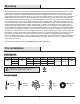
Warranty We warrant the fan motor to be free from defects in workmanship and material present at time of shipment from the factory for a period of lifetime after the date of purchase by the original purchaser. We also warrant that all other fan parts, excluding any glass or acrylic blades, to be free from defects in workmanship and material at the time of shipment from the factory for a period of one year after the date of purchase by the original purchaser.
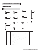
Pre-Installation (continued) HARDWARE INCLUDED NOTE: Hardware shown to actual size unless noted otherwise in the table below.
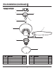
Pre-Installation (continued) PACKAGE CONTENTS A B C E D G F H I J Part Description Quantity Part Description Quantity F Fan motor assembly 1 A Mounting bracket (preassembled) 1 B Canopy ring 1 G Blades 5 C Canopy 1 H Blade arms 5 D Canopy bottom cover 1 I Light kit 1 E Hanger ball/downrod assembly 1 J Glass shade 1 6
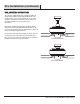
Pre-Installation (continued) DUAL MOUNTING INSTRUCTIONS This ceiling fan is supplied with two types of hanging assemblies: the standard ceiling installation using the downrod with ball and socket mounting, and the "close-to-ceiling" mounting. The "close-to-ceiling" mounting is recommended in rooms with less than 8 ft. ceilings or in areas where additional space is desired from the floor to the fan blades.
Installation MOUNTING OPTIONS WARNING: To reduce the risk of fire, electric shock, or personal injury, mount the fan to an outlet box marked acceptable for fan support using the screws provided with the outlet box. An outlet box commonly used for the support of lighting fixtures may not be acceptable for fan support and may need to be replaced. If in doubt, consult a qualified electrician. NOTE: You may need a longer downrod to maintain proper blade clearance when installing on a steep, sloped ceiling.
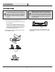
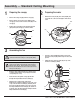
Assembly — Standard Ceiling Mounting 1 2 Preparing the canopy □ Remove the canopy ring (B) from the canopy (C). □ Remove the two non-slotted screws (BB) from the canopy (C), and loosen the slotted screws (BB) on the canopy (C). □ □ Preparing the motor Remove the clevis pin (CC), and cotter pin (DD), and loosen the two collar setscrews (EE) from the motor collar. DD Remove the canopy (C) from the mounting bracket (A) by turning the canopy (C) counterclockwise.
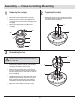
Assembly — Close-to-Ceiling Mounting 1 2 Preparing the canopy □ Remove the canopy ring (B) from the canopy (C). □ Remove the two non-slotted screws (BB) from the canopy (C), and loosen the slotted screws (BB) on the canopy (C). □ Remove the canopy bottom cover (D) from the canopy (C). Preparing the motor □ Remove three of the six collar mounting screws with lock washers (FF) (every other one) from the collar on top of the fan motor assembly (F).
Assembly — Hanging the Fan Attaching the fan to the electrical box 4 WARNING: To reduce the risk of fire, electric shock or other personal injury, mount the fan only to an outlet box or supporting system marked acceptable for fan support and use the mounting screws provided with the outlet box. □ Pass the 120-volt supply wires through the center hole in the mounting bracket (A).
Assembly — Hanging the Fan (continued) 6 Making the electrical connections SS RR QQ WARNING: To avoid possible electrical shock, be sure electricity is turned off at the main fuse box before wiring. WARNING: Check to see that all connections are tight, including ground, and that no bare wire is visible at the wire nuts (except for the ground wire). NN AA Follow the steps below to connect the fan to your household wiring. Use the plastic wire nuts (AA) with your fan.
Assembly — Hanging the Fan (continued) 7a 7b Standard ceiling mounting WARNING: Locking slots of the canopy (C) are provided only as an aid to mounting. Do not leave the fan assembly unattended until all four canopy screws are engaged and firmly tightened. WARNING: Make sure the tab on the mounting bracket (A) properly sits in the groove in the hanger ball (E) before attaching the canopy (C) to the mounting bracket (A) by turning the canopy housing until it drops into place.
Assembly — Attaching the Fan Blades 8 □ Removing the rubber packing mounts The fan motor assembly (F) is shipped with rubber packing mounts (XX) to prevent movement during transportation. Remove the five rubber packing mounts (XX) from the fan motor assembly (F) and discard prior to attaching the blade arms.
Assembly — Attaching the Fan Blades (continued) 10 Fastening the blade assemblies to the motor WARNING: To reduce the risk of personal injury, do not bend the blade arms (H) while installing, balancing the blades (G), or cleaning the fan. Do no insert foreign objects between rotating fan blades (G). □ Fasten the blade assemblies to the fan motor assembly (F) by lining up the slots of the motor (DDD) with the tabs on the blade arms (EEE).
Assembly — Installing the Light Kit 11 Attaching the light kit to the switch housing 12 Mounting the glass shade CAUTION: Before starting the installation, disconnect the power by turning off the circuit breaker or removing the fuse at the fuse box. Turning power off using the fan switch is not sufficient to prevent electric shock. □ □ □ Remove the three light kit mounting screws (HH) from the light kit (I) and keep these screws.
Assembly Operation — Installing the Light Kit (continued) 13 Installing the fan without the light kit (optional) □ Disassemble the switch housing cover (GGG) from the light kit. You can keep the light kit for future use. □ Attach the plastic plug (MM) to the switch housing cover (GGG). □ Install the switch housing cover (GGG) to the switch housing with light kit mounting screws (HH) provided. F HH GGG MM 17 HAMPTONBAY.COM Please contact 1-855-HD-HAMPTON for further assistance.
Operation PULL CHAIN OPERATING INSTRUCTIONS Install two pull chains and fobs (LL]) onto the pull chains located in the switch housing and light kit (I). Turn on the power and check the operation of the fan. The pull chain controls the fan speed as follows: 1 pull - High, 2 pulls - Medium, 3 pulls - Low, and 4 pulls - Off. Speed settings for warm or cool weather depend on factors such as the room size, ceiling height, and number of fans.
Care and Cleaning Do □ Do not Check the support connections, brackets, and blade attachments twice a year. Make sure they are secure. Because of the fan’s natural movement, some connections may become loose over time. It is not necessary to remove the fan from the ceiling. □ Clean your fan periodically. Use only a soft brush or lint-free cloth to avoid scratching the finish. The plating is sealed with a lacquer to minimize discoloration or tarnishing.
Troubleshooting (continued) Problem Solution □ Verifica que todas las aspas y los tornillos de los soportes de aspas estén seguros (la mayoría de los problemas de oscilación del ventilador se deben a piezas sueltas). Una vez que el ventilador ha sido instalado correctamente, enciéndelo durante 10 minutos para que se autoajuste. Si luego de 10 minutos de estar encendido el ventilador aún oscilara, verifica el nivel de las aspas utilizando el siguiente procedimiento: The fan wobbles.
Service Parts AA A II F BB JJ KK B CC G C H I LL DD EE FF D MM GG J E HH Description Part Description A Mounting bracket (preassembled) AA Plastic wire nut B Canopy ring (preassembled) BB Canopy mounting screw with lock washer (preassembled) C Canopy CC Clevis pin (preassembled) D Canopy bottom cover (preassembled) DD Cotter pin (preassembled) E Hanger ball/downrod assembly EE Collar setscrews (preassembled) F Fan motor assembly FF Collar mounting screws with lock
Questions, problems, missing parts? Before returning to the store, call Hampton Bay Customer Service 8 a.m. - 6 p.m., EST, Monday-Friday 1-855-HD-HAMPTON HAMPTONBAY.COM Retain this manual for future use.