
Instructions / Assembly

Page 19
AVERTISSEMENT:
1. Avant de commencer à installer ce luminaire ou d'enlever l'ancien luminaire,
déconnectez le courant en éteignant le disjoncteur ou en enlevant le fusible
correspondant du coffret à fusibles.
2.
CONSULTER UN ELECTRICIEN QUALIFIE POUR TOUTE
QUESTION RELATIVE A L'ELECTRICITE.
3.
La luminosité de l’ampoule électrique fluorescente compacte GU-24
fournie avec ce luminaire n’est pas modulable. Ne pas utiliser de dispositif
de modulation de luminosité avec ce luminaire.
4.
En cas de questions non relatives à l'électricité à propos de ce luminaire,
veuillez contacter notre centre de Service à la Clientèle au 1-877-527-0313
ou visiter www.homedepot.com. Veuillez indiquer votre
UGS
395-250 ou
UPC 6940500311029.
5.
Conserver votre reçu et ces Instructions comme Preuve d'Achat.
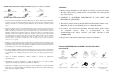
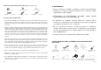
OUTILS REQUIS POUR L'ASSEMBLAGE & L'INSTALLATION
(non inclus):
Ampoule ( inclus) Lunettes de Protection Echelle Gants Dénudeur de câbles
(13 watts maxima) électriques
Tournevis à tête Plate Tournevis à croisillon Ruban adhésif Pince pour Joint en Caoutchouc Silicone
isolant câbles électriques pour un usage extérieur
Page 6
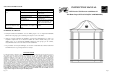
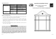
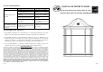
PARTS INCLUDED FOR INSTALLATION (parts are not to scale):
2ea Lock Nuts (#5) 3ea Wire Connectors (#8) 1ea Cross Bar (#9)
2ea Outlet Box Screws (#10) 1ea Ground Screw (#11) 2ea Mounting Screws (#12)
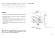
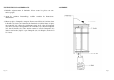
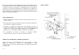
INSTALLATION INSTRUCTIONS:
1. Screw the two Mounting Screws (#12) into the Cross Bar (#9). Mount the Cross Bar (#9) to
the Outlet Box (#7) using the two Outlet Box Screws (#10). [Make sure the threads of the
Mounting Screws (#12) are facing outside when the Cross Bar (#9) is attached to the Outlet
Box (#7).]
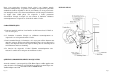
2. Wrap the ground wire from the fixture around the Ground Screw (#11) on the Cross Bar (#9),
and then connect the ground wire from the fixture to the ground wire from the Outlet Box (#7).
Connect the white wire from the fixture to the white wire from the Outlet Box (#7), and the
black wire from the fixture to the black wire from the Outlet Box (#7). Cover the three wire
connections using the three Wire Connectors (#8). Wrap the three wire connections with
electrical tape for a more secure connection. Position the wires back inside the Outlet Box
(#7). Note: If you have questions, consult your local electrical code for approved grounding
methods.
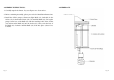
3. Mount the body of the fixture on the wall by aligning the protruding Mounting Screws (#12)
all the way through the holes in the Wall Plate (#1). Be careful not to pinch any of the wires
between the fixture and the Outlet Box (#7). Tighten the fixture to the wall by screwing the
two Lock Nuts (#5) onto the two protruding Mounting Screws (#12).
4. Once the fixture is mounted on the wall, caulk the space between the wall and the upper 3/4
area of the Wall Plate (#1) to prevent water seeping into the Outlet Box (#7). Leave the
bottom 1/4 area uncaulked for drainage of any water which might leak into the enclosure.
5. Before completing Installation, please return to the Assembly Instruction #3.
6. Installation is complete. Turn on the power at the circuit breaker or fuse box. Turn the light
switch on to activate the fixture.
7. If it is daylight, the light bulb will not illuminate. To test the fixture, cover the Photocell (#2)
with electrical tape to illuminate the light bulb. Once you confirm the light bulb illuminates,
remove the electrical tape.