Item #316-622 Model #BPT18-34ALE-2 Item #316-183 Model #BPT18-54AL-1 USE AND CARE GUIDE VENTILATION FAN Questions, problems, missing parts? Before returning to the store, call Hampton Bay Customer Service 8 a.m. - 6 p.m., EST, Monday-Friday 1-855-HD-HAMPTON HAMPTONBAY.COM THANK YOU We appreciate the trust and confidence you have placed in Hampton Bay through the purchase of this ventilation fan. We strive to continually create quality products designed to enhance your home.
Table of Contents Table of Contents .......................................................... 2 Safety Information......................................................... 2 Warranty ......................................................................... 3 Pre-installation .............................................................. 3 Planning Installation ................................................................3 Installation Options .............................................................
Warranty If this product fails due to a defect in materials or workmanship at any time during the first three years of ownership, the manufacturer will replace it free of charge, postage-paid at their option. This warranty does not cover products which have been abused, altered, damaged, misused, cut or worn. This warranty does not cover use in commercial applications.
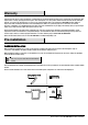
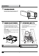
Pre-installation (continued) INSTALLATION OPTIONS We recommend installing the ventilation fan by securing the main body of the fan against one ceiling joist and using the header bars as necessary for support of the adjoining joist. There are multiple installation configurations possible for this ventilation fan. Not all configurations are shown. If your installation requires a variation other than those shown, consult with a licensed contractor to determine the best installation for your project.
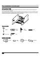
Pre-installation (continued) HARDWARE INCLUDED NOTE: Hardware not shown to actual size.
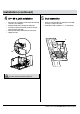
Installation 1 Determining joist width □ Measure the distance from the center of the two ceiling joists where you will be installing the ventilation fan. 2 Suspension bracket installation □ □ □ □ □ 3 Joint installation under 20 in. □ For ceiling joist installations under 20 in., insert suspension bracket I (D) into the fan body (A). Proceed to step 3. For ceiling joist installations between 20 in. and 24 in., insert suspension brackets I (D), II (E), and III (F). Proceed to step 4.
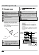
Installation (continued) 4 20 – 24 in. joist installation □ □ □ □ □ 5 Duct connection □ Use long wood screws (BB) to loosely attach the main body of the fan to one ceiling joist. Extend the hanger bars to the opposite ceiling joist. Secure the suspension brackets (D, E, and F) to the joist using long wood screws (BB). Ensure the main body is level and square to the joists. Tighten all screws. □ Install a circular duct (W) to the outlet and secure it with duct tape or clamps to the outlet.
Installation (continued) 6 7 Using quick connect WARNING: Wiring must comply with all applicable electrical codes. Turn OFF power before removing or installing connectors. WARNING: Make sure that the main power is off WARNING: COPPER TO COPPER ONLY. Do not use on Aluminum wire. WARNING: Failure to wire this product correctly could result in electrical shock, fire hazards, or damage to the product. Consult a licensed electrician if you are unsure of your ability to correctly install wiring.
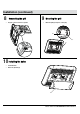
Installation (continued) 8 □ 9 Mounting the grill Connecting the grill □ Plug the connector into the receptacle. Mount the grill (B) using the screws (CC). CC CC B 10 Installing the bulbs □ □ Install the bulbs. Attach the grill lens (C). C 9 HAMPTONBAY.COM Please contact 1-855-HD-HAMPTON for further assistance.
Care and Cleaning □ □ □ □ □ □ □ □ Before servicing or cleaning the unit, disconnect the power supply at the panel and lock to prevent the power from being turned on. If the panel cannot be locked, clearly mark the panel with a warning tag to prevent the power from being turned on. Remove the grill by squeezing the springs and pulling the grill down. Wash and clean the grill in a sink and dry with a cloth. Remove dust and dirt from the fan housing with a vacuum cleaner.
Specifications BPT18-34ALE-2 Model No. BPT18-34ALE-2 Air direction 110 cfm Voltage 120 V Hertz 60 HZ Duct diameter 6 in. (15 cm) Noise 0.8 Sone Power consumption (Watts) 32 W Speed 732 rpm Air deliver at 0.1" WG 110 cfm Weight 14.12 lbs. (6.42 Kg) BPT18-54AL-1 Model No. BPT18-54AL-1 Air direction 140 cfm Voltage 120 V Hertz 60 HZ Duct diameter 6 in. (15 cm) Noise 1.1 Sone Power consumption (Watts) 41 W Speed 811 rpm Air deliver at 0.1" WG 140 cfm Weight 14.12 lbs. (6.
Service Parts BPT18-34ALE-2 SERVICEABLE PARTS ABPTAL3404 ABPTAL05604 ABPTAL5603 BGBPT18010 HM0000004 UB40403001 HTSQL0003 HTBPT1801 UC40401002 Part Number HM0000004 UB40403001 UC40400802 ABPTAL5603 ABPTAL3404 UC40401201 Description Quick connectors Long wood screws (M4x30) Short screws (M4x8) Grill, lamp box and sockets, and spring clip Complete assembled fan and housing Short screws (M4x12) UC40400802 UC40401201 Quantity Part Number 7 8 1 1 ABPTAL05604 BGBPT18010 HTBPT1801 HTSQL0003 1 UC4
Service Parts (continued) BPT18-54AL-1 SERVICEABLE PARTS ABPTAL5601 ABPTAL05604 BPTAL5603 BGBPT18010 HM0000004 UB40403001 HTSQL0003 HTBPT1801 UC40401002 Part Number HM0000004 UB40403001 UC40400802 ABPTAL5603 ABPTAL5601 UC40401201 Description Quick connectors Long wood screws (M4x30) Short screws (M4x8) Grill, lamp box and sockets, and spring clip Complete assembled fan and housing Short screws (M4x12) UC40400802 UC40401201 Part Number Description 7 8 1 1 ABPTAL05604 BGBPT18010 HTBPT1801 HTSQL
Questions, problems, missing parts? Before returning to the store, call Hampton Bay Customer Service 8 a.m. - 6 p.m., EST, Monday-Friday 1-855-HD-HAMPTON HAMPTONBAY.COM Retain this manual for future use.
Artículo núm. 316-622 Modelo núm.BPT18-34ALE-2 Artículo núm. 316-183 Modelo núm.BPT18-54AL-1 GUÍA DE USO Y MANTENIMIENTO VENTILADOR ¿Preguntas, problemas o piezas faltantes? Antes de regresar a la tienda, llama al Servicio al Cliente de Hampton Bay de 8 a.m. a 6 p.m., Hora Estándar del Este, de Lunes a Viernes 1-855-HD-HAMPTON HAMPTONBAY.COM GRACIAS Apreciamos tu seguridad y confianza que ha depositado en Hampton Bay a través de la compra de este ventilador.
Índice Instalación ...................................................................... 20 Cuidado y Limpieza ...................................................... 24 Especificaciones ........................................................... 25 BPT18-34ALE-2............................. .............................. 25 BPT18-54AL-1 ........................................................... 25 Dimensiones (BPT18-34ALE-2 y BPT18-54AL-1)....... 25 Índice ................................................
Garantía Si este producto falla debido a un defecto de material o mano de obra, en cualquier momento durante los primeros tres años de uso, el fabricante lo reemplazará sin cargo alguno y con franqueo pagado, a su discreción. Esta garantía no cubre productos que hayan sido maltratados, alterados, dañados, usados incorrectamente, cortados o gastados. Esta garantía no cubre usos comerciales.
Pre-Instalación (continuación) OPCIONES DE INSTALACIÓN Recomendamos instalar el ventilador asegurando el cuerpo principal del ventilador contra una viga del techo y usando las barras del cabezal según sea necesario para soportar la viga contigua. Existen múltiples configuraciones de instalación posibles para el ventilador. No se muestran todas las configuraciones.
Pre-Instalación (continuación) HERRAJES INCLUIDOS NOTA: Se muestra el tamaño real de los herrajes.
Instalación 1 Determinar el ancho de la viga □ Mide la distancia desde el centro de las dos vigas del techo donde instalarás el ventilador. Instalación del soporte de suspensión 2 □ 3 Para instalaciones de viga a menos de 50,8 cm, inserta el soporte de suspensión I (D) en el cuerpo del ventilador (A). Procede con el paso 3. Para instalaciones de viga entre 50,8 cm y 60,96 cm, inserta los soportes de suspensión I (D), II (E) y III (F). Procede con el paso 4.
Instalación (continuación) 4 □ □ □ □ □ Instalación de la viga de 50,8 cm 60,96 cm 5 Conexión del ducto □ Usa tornillos de madera largos (BB) para unir sin apretar el cuerpo principal del ventilador a una viga del techo. Extiende las barras de suspensión a la viga opuesta del techo. Asegura los soportes de suspensión (D, E y F) a la viga mediante los tornillos de madera largos (BB). Asegúrate de que el cuerpo principal esté a nivel y a escuadra de las vigas. Ajusta todos los tornillos.
Instalación (continuación) 6 Cómo usar el conector rápido 7 ADVERTENCIA: El cableado debe cumplir con todos los códigos eléctricos pertinentes. APAGA la electricidad antes de retirar o instalar los conectores. ADVERTENCIA: Asegúrate de que la electricidad esté apagada. ADVERTENCIA: Si el producto no es conectado correctamente, puede causar en una descarga eléctrica, riesgo de incendio, o daño al producto. Consulta a un técnico electricista si no estás seguro de cómo instalar correctamente el cableado.
Instalación (continuación) 8 Cómo colocar la rejilla. □ 9 Enchufa el conector al receptáculo. Cómo instalar la rejilla □ Monta la rejilla (B) con los tornillos (CC). 10 Cómo instalar las bombillas □ Instala la bombilla. □ Sujeta la lente de la rejilla (C). C 23 www.hamptonbay.
Cuidado y Limpieza □ Antes de revisar o limpiar la unidad, desconecta el suministro de electricidad en el panel y cierra con llave el panel para evitar que activen la corriente. Si no se puede cerrar con llave el panel, márcalo claramente con una etiqueta de advertencia para evitar que activen corriente. □ Quita la rejilla apretando los resortes y empujando hacia abajo. □ Lava y limpia la parrillla en un fregadero y seca con un paño.
Especificaciones BPT18-34ALE-2 Modelo Núm. BPT18-34ALE-2 Dirección del aire 110 cfm Voltaje 120 V Hertz 60 HZ Diámetro del ducto 6 plg (15 cm) Ruido 0,8Sonio Consumo de energía (Vatios) 32 W Velocidad 732rpm Emisión del aire a 0,1" WG 110 cfm Peso 14,12 lb (6,42 kg) BPT18-54AL-1 Modelo Núm.
Piezas de repuesto BPT18-34ALE-2 PIEZAS REPARABLES ABPTAL3404 ABPTAL05604 ABPTAL5603 BGBPT18010 HM0000004 UB40403001 HTSQL0003 UC40401002 Número de pieza Descripción UC40400802 HTBPT1801 UC40401201 Cantidad Número de pieza HM0000004 Conectores rápidos 7 ABPTAL05604 Soporte de suspensión completo 1 UB40403001 Tornillos de madera largos (M4X30) 8 Lente de rejilla 1 UC40400802 Tornillos Cortos (M4X8) 1 BGBPT18010 HTBPT1801 Bombilla GU24 CFL de 13W 2 ABPTAL5603 1 HTSQL0003 ABP
Piezas de repuesto (continuación) BPT18-54AL-1 PIEZAS REPARABLES ABPTAL5601 ABPTAL05604 ABPTAL5603 BGBPT18010 HM0000004 UB40403001 HTSQL0003 HTBPT1801 UC40401002 Número de pieza Descripción UC40400802 UC40401201 Cantidad Número de pieza HM0000004 Conectores rápidos 7 ABPTAL05604 Soporte de suspensión completo 1 UB40403001 Tornillos de madera largos (M4X30) 8 1 UC40400802 Tornillos Cortos (M4X8) 1 BGBPT18010 HTBPT1801 Lente de rejilla Bombilla GU24 CFL de 13W 2 ABPTAL5603 1 HT
¿Preguntas, problemas o piezas faltantes? Antes de regresar a la tienda, llama al Servicio al Cliente de Hampton Bay de 8 a.m. a 6 p.m., Hora Estándar del Este, de Lunes a Viernes 1-855-HD-HAMPTON HAMPTONBAY.COM Conserva este manual para referencias futuras.
Article n° 316-622 Modèle n° BPT18-34ALE-2 Article n° 315-888 Modèle n°n° BPT18-54AL-1 GUIDE D'UTILISATION ET D'ENTRETIEN VENTILATEUR D'AÉRATION Questions, problèmes, pièces manquantes? Avant de retourner au magasin, veuillez communiquer avec le service à la clientèle Hampton Bay entre 8 h et 18 h, HNE, du lundi au vendredi 1-855-HD-HAMPTON HAMPTONBAY.COM MERCI Nous apprécions la confiance que vous avez placée en Hampton Bay grace à l'achat de ce ventilateur.
Table des matières Table des matières........................................................ 30 Consignes de sécurité ................................................. 30 Garantie........................................................................... 31 Pré-installation............................................................... 31 Préparation de I'installation ..................................... 31 Options d’installation.................................................. 32 Outils requis..........
Garantie Si ce produit tombe en panne du fait d'un vice de fabrication ou d'un vice de matériaux à un moment quelconque pendant les trois premières années de possession par l'acheteur, le fabricant le remplacera gratuitement, en port-payé à sa discrétion. Cette garantie ne couvre pas les produits qui ont été abusés, modifiés, endommagés, mal utilisés, coupés ou usés. Cette garantie ne couvre pas un usage commercial du produit.
Pré-installation (suite) OPTIONS D’INSTALLATION Nous vous recommandons d'installer le ventilateur d'aération en fixant le corps principal du ventilateur contre une solive du plafond et en utilisant les barres de chevêtre comme nécessaire pour supporter la solive adjacente. Il existe de nombreuses configurations d'installation pour ce ventilateur d'aération. Toutes les configurations ne sont pas illustrées.
Pré-installation (suite) QUINCAILLERIE FOURNIE REMARQUE : Quincaillerie illustrée à la grandeur nature.
Installation Détermination de la largeur entre les solives 1 □ 2 □ □ □ □ □ Mesurez la distance centre à centre entre deux solives de plafond là où vous voulez installer le ventilateur d'aération. Installation du support de suspension 3 Pour des installations sur des solives écartées de moins de 50,80 cm (20 po), insérez le support de suspension I (D) dans le corps du ventilateur (A). Passez à l'étape 3.
Installation (suite) Installation entre des solives écartées de 50,80 à 60,96 cm (20 à 24 po) 4 □ □ □ □ □ Utilisez des vis à bois longues (BB) pour attacher de manière lâche le corps principal du ventilateur à l'une des solives de plafond. Allongez les barres de suspension vers la solive de plafond opposée. Fixez les supports de suspension (D, E et F) sur la solive à l'aide de vis à bois longues (BB). Vérifiez que le corps principal est de niveau et d'équerre par rapport aux solives.
Installation (suite) 6 7 Utilisation d'un connecteur rapide MISE EN GARDE : Le câblage doit être conforme à tous les codes électriques applicables. Coupez le courant électrique avant de retirer ou d'installer les connecteurs. MISE EN GARDE : Assurez-vous que le courant électrique est coupé. MISE EN GARDE : Un câblage incorrect de ce produit pourrait entraîner des chocs électriques, un risque d'incendie ou un endommagement du produit.
Installation (suite) 8 Raccordement de la grille □ Branchez le connecteur dans la prise. 9 Montage de la grille □ Montez la grille (B) à l'aide des vis (CC). 10 Installation des ampoules □ Installez l'ampoule □ Attachez le diffuseur (C). C www.hamptonbay.com 37 Veuillez composer le 1-855-HD-HAMPTON pour une assistance supplé mentaire.
Entretien et nettoyage □ Avant d'entretenir ou de nettoyer l'unité, coupez le courant électrique au tableau et verrouillez le tableau pour éviter que le courant ne soit remis. Si le tableau ne peut pas être verrouillé, affichez un avertissement bien visible sur le tableau pour empêcher que le courant ne soit rétabli. □ Retirez la grille en comprimant les ressorts et en tirant la grille vers le bas. □ Lavez et nettoyez la grille dans l'évier et séchez-la avec un linge.
Caractéristiques BPT18-34ALE-2 Modèle N° BPT18-34ALE-2 Direction de l'air 110 pieds cubes par minute Tension 120 V Hertz 60 Hz Diamètre du conduit 15,24 cm (6 po) Bruit 0,8 Sone Consommation électrique (watts) 32 W Rapidité 732 tr/min Débit de l'air fourni à 0,1 po WG 110 pieds cubes par minute Poids 6,42 kg (14,12 lb) BPT18-54AL-1 Modèle N° BPT18-54AL-1 Direction de l'air 140 pieds cubes par minute Tension 120 V Hertz 60 Hz Diamètre du conduit 15,24 cm (6 po) Bruit 1,1 Sone
Pièces de rechange PIÈCES DE RECHANGE POUR BPT18-34ALE-2 ABPTAL3404 ABPTAL05604 ABPTAL5603 BGBPT18010 HM0000004 UB40403001 HTSQL0003 HTBPT1801 UC40401002 Pièce n° Description UC40400802 UC40401201 Quantité Pièce n° HM0000004 Connecteurs rapides 7 ABPTAL05604 Support de suspension complet 1 UB40403001 Vis à bois longues (M4X30) 8 BGBPT18010 Diffuseur 1 UC40400802 Vis courtes (M4X8) 1 HTBPT1801 Ampoule fluocompacte GU24 de 13 W 2 ABPTAL5603 1 HTSQL0003 ABPTAL3404 Grille, bo
Pièces de rechange (suite) PIÈCES DE RECHANGE POUR BPT18-54AL-1 ABPTAL5601 ABPTAL05604 ABPTAL5603 BGBPT18010 HM0000004 UB40403001 HTSQL0003 HTBPT1801 UC40401002 Pièce n° Description UC40400802 UC40401201 Quantité Pièce n° HM0000004 Connecteurs rapides 7 ABPTAL05604 Support de suspension complet 1 Description Quantité UB40403001 Vis à bois longues (M4X30) 8 BGBPT18010 Diffuseur 1 UC40400802 Vis courtes (M4X8) 1 HTBPT1801 Ampoule fluocompacte GU24 de 13 W 2 ABPTAL5603 1 HTS
Questions, problèmes, pièces manquantes? Avant de retourner au magasin, veuillez communiquer avec le service à la clientèle Hampton Bay entre 8 h et 18 h, HNE, du lundi au vendredi 1-855-HD-HAMPTON HAMPTONBAY.COM Conservez ce guide pour un usage ultérieur.