Item #316-622 Model #BPT18-34ALE-1 Item #316-183 Model ##BPT18-54AL USE AND CARE GUIDE VENTILATION FAN READ AND SAVE THESE INSTRUCTIONS Questions, problems, missing parts? Before returning to the store, call Hampton Bay Customer Service 8 a.m.-6 p.m., EST, Monday-Friday 1-877-527-0313 HAMPTONBAY.COM THANK YOU We appreciate your trust and confidence in Hampton Bay with your purchase of this ventilation fan.
Table of Contents Table of Contents ............................................................ 2 Installation.........................................................................7 Safety Information........................................................... 2 Care and Cleaning......................................................... 11 Warranty ........................................................................... 3 Specifications .............................................................
Safety Information (Continued) WARNING: Not suitable for use as a range hood or in areas where hazardous or explosive vapors are present. CAUTION: For General Ventilating Use only.Do not Use To Exhaust Hazardous Or Explosive Materials And Vapors. WARNING: FOR USE IN NON FIRE-RELATED INSTALLATIONS ONLY. IMPORTANT: Exercise care to not damage existing wiring when cutting or drilling into walls or ceilings. WARNING: FOR USE IN ONE-AND-TWO FAMILY DWELLINGS ONLY.
Pre-Installation PLANNING FOR SUCCESSFUL INSTALLATION Do not install the ventilation fan in areas where the duct work will require configurations as shown in the following figure: When installing the ventilation fan in a new construction site, install the main body of the fan and duct work during the rough‑in construction of the building. The grill should be installed after the finished ceiling is in place.
Pre-Installation (continued) TOOLS REQUIRED Hammer Safety goggles Phillips screwdriver Duct clamp Duct tape Level Electrical tape Drill MATERIALS REQUIRED Duct vent Duct piping HARDWARE INCLUDED NOTE: Hardware shown to actual size. Part AA BB CC Description Quick connect Long wood screw Screw Quantity 7 8 7 5 www.hamptonbay.com Please contact 1-877-527-0313 for further assistance.
Pre-Installation (continued) PACKAGE CONTENTS Part Description Part Description A Fan body E Suspension bracket II B Grill F Suspension bracket III C Grill lens G 4W incandescent night light D Suspension bracket I H GU24 13W CFL bulb 6
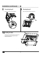
Installation 1 Determining joist width Measure the distance from the center of the two ceiling joists where you will be installing the ventilation fan. 2 Suspension bracket installation □ □ 3 For ceiling joist installations under 20 in., insert suspension bracket I (D) into the fan body (A). Proceed to step 3. For ceiling joist installations between 20 in. and 24 in., insert suspension brackets I (D), II (E), and III (F). Proceed to step 4. Joint installation under 20 in.
Installation (continued) 4 5 20 – 24 in. joist installation □ □ □ □ □ Use long wood screws (BB) to loosely attach the main body of the fan to one ceiling joist. Extend the hanger bars to the opposite ceiling joist. Secure the suspension brackets (D, E, and F) to the joist using long wood screws (BB). Ensure the main body is level and square to the joists. Tighten all screws. Duct connection □ □ CAUTION: Do not mount the fan flush against the joist. The flange should be flush with the ceiling board.
Installation (continued) 6 Using quick connect Connecting wiring from unit to house 7 WARNING: Wiring must comply with all applicable electrical codes. Turn OFF power before removing or installing connectors. WARNING: Make sure that the main power is off. WARNING: COPPER TO COPPER ONLY. Do not use on Aluminum wire. WARNING: Failure to wire this product correctly could result in electrical shock, fire hazards, or damage to the product.
Installation (continued) 8 Connecting the grill □ 9 Plug the connector into the receptacle. □ 10 Installing the bulbs □ □ Mounting the grill Install the 4w incandescent bulb (G) and the 13w CFL bulbs (H) into their respective sockets. Attach the grill lens (C). 10 Mount the grill (B) using the screws (CC).
Care and Cleaning □ □ CAUTION: Do not use solvents, thinner or harsh chemicals for cleaning the fan. Before servicing or cleaning the unit, disconnect the power supply at the panel and lock to prevent the power from being turned on. If the panel cannot be locked, clearly mark the panel with a warning tag to prevent the power from being turned on. CAUTION: Do not allow water to enter the motor.
Specifications BPT18-34ALE-1 Model No. BPT18-34ALE-1 Air direction 110 cfm Voltage 120 V Hertz 60 HZ Duct diameter 4 in. (10.16 cm) Noise 1.2 Sone Power consumption (Watts) 33 W Speed 815 rpm Air deliver at 0.1" WG 110 cfm Weight 14.12 lbs. (6.42 Kg) BPT18-54AL Model No. BPT18-54AL Air direction 140 cfm Voltage 120 V Hertz 60 HZ Duct diameter 4 in. (10.16 cm) Noise 1.5 Sone Power consumption (Watts) 48 W Speed 935 rpm Air deliver at 0.1" WG 140 cfm Weight 14.12 lbs.
Service Parts BPT18-34ALE-1 SERVICEABLE PARTS = Part number Description Quantity HM0000004 Quick connectors 7 UB40403001 Long wood screws 8 UC40400802 Short screws 7 ABPTAL5603 Grill, lamp box and sockets, and spring clip 1 ABPTAL3404 Complete assembled fan and housing 1 ABPTAL05604 Complete suspension bracket 1 BGBPT18010 Grill lens 1 HTBPT1801 GU24 13W CFL bulb 2 HTSQL0003 4W incandescent night light 1 13 www.hamptonbay.
Service Parts (continued) BPT18-54AL SERVICEABLE PARTS Part number Description Quantity HM0000004 Quick connectors 7 UB40403001 Long wood screws 8 UC40400802 Short screws 7 ABPTAL5603 Grill, lamp box and sockets, and spring clip 1 ABPTAL5601 Complete assembled fan and housing 1 ABPTAL05604 Complete suspension bracket 1 BGBPT18010 Grill lens 1 HTBPT1801 GU24 13W CFL bulb 2 HTSQL0003 4W incandescent night light 1 14
This page intentionally left blank 15 www.hamptonbay.com Please contact 1-877-527-0313 for further assistance.
Questions, problems, missing parts? Before returning to the store, call Hampton Bay Customer Service 8 a.m.-6 p.m., EST, Monday-Friday 1-877-527-0313 HAMPTONBAY.COM Retain this manual for future use.
Artículo núm. 316-622 Model núm.BPT18-34ALE-1 Artículo núm. 316-183 Modelo núm.BPT18-54AL CGUÍA DE USO Y MANTENIMIENTO VENTILADOR REPASE Y GUARDE ESTAS INSTRUCCIONES ¿Preguntas, problemas o piezas faltantes? Antes de regresar a la tienda, llama al Servicio al Cliente de Hampton Bay de 8 a.m. a 6 p.m., Hora Estándar del Este, de Lunes a Viernes 1-877-527-0313 HAMPTONBAY.COM GRACIAS Apreciamos tu seguridad y confianza en Hampton Bay al comprar este ventilador.
Índice Índice ............................................................................... 18 Instalación ...................................................................... 23 Información de Seguridad ........................................... 18 Cuidado y Limpieza ...................................................... 27 Garantía........................................................................... 19 Especificaciones ...........................................................
Información de Seguridad (continuación) ADVERTENCIA: No es adecuado para usar como campana de extracción o en lugares donde haya vapores peligrosos o explosivos. PRECAUCIÓN: Para Uso de Ventilación General Solamente. No lo Uses para Expulsar Vapores o Materiales Peligrosos o Explosivos. ADVERTENCIA: SÓLO PARA USO EN INSTALACIONES SIN CLASIFICACIÓN CONTRA INCENDIOS. IMPORTANTE: Al cortar o taladrar en una pared o techo, ten cuidado de no dañar el cableado existente.
Pre-Instalación PLANIFICAR UN ENSAMBLADO EXITOSO Cuando instales el ventilador en un nuevo sitio de construcción, instala el cuerpo principal del ventilador y la red de conductos durante la instalación de las tuberías del edificio. La rejilla se debe instalar después de que el techo terminado esté en su lugar.
Pre-Instalación (continuación) HERRAMIENTAS NECESARIAS Gafas de seguridad Martillo Cinta de electricista Destornillador Phillips Nivel Taladro MATERIALES NECESARIOS Ducto de Ventilación Cinta para ducto Abrazadera para ducto Tubería para ducto HERRAJES INCLUIDOS NOTA: Se muestra el tamaño real de los herrajes. Pieza AA BB CC Descripción Conector Rápido Tornillo de madera largo Tornillo Cantidad 7 8 7 21 www.hamptonbay.com Para obtener asistencia, llama al 1-877-527-0313.
Pre-Instalación (continuación) CONTENIDO DEL PAQUETE Pieza Descripción Pieza Descripción A Cuerpo del ventilador E Soporte de suspensión II B Rejilla F Soporte de suspensión III C Lente de rejilla G Lámpara nocturna incandescente de 4W D Soporte de suspensión I H Bombilla GU24 CFL de 13W 22
Instalación 1 Determinar el ancho de la viga Mide la distancia desde el centro de las dos vigas del techo donde instalarás el ventilador. Instalación del soporte de suspensión 2 □ □ Instalación de la viga menores a 50,8 cm 3 Para instalaciones de viga a menos de 50,8 cm, inserta el soporte de suspensión I (D) en el cuerpo del ventilador (A). Procede con el paso 3. Para instalaciones de viga entre 50,8 cm y 60,96 cm, inserta el soporte de suspensión I (D), II (E) y III (F). Procede con el paso 4.
Instalación (continuación) Instalación de la viga de 50,8 cm 60,96 cm 4 □ □ □ □ □ 5 Usa tornillos de madera largos (BB) para unir sin apretar el cuerpo principal del ventilador a una viga del techo. Extiende las barras de suspensión a la viga opuesta del techo. Asegura los soportes de suspensión (D, E y F) a la viga mediante los tornillos de madera largos (BB). Asegúrate de que el cuerpo principal esté a nivel y a escuadra de las vigas. Ajusta todos los tornillos.
Instalación (continuación) 6 Cómo usar el conector rápido Cómo conectar el cableado de la unidad a la casa 7 ADVERTENCIA: El cableado debe cumplir con todos los códigos eléctricos pertinentes. Apaga la electricidad antes de retirar o instalar los conectores. ADVERTENCIA: Asegúrate de que la electricidad esté apagada. ADVERTENCIA: Si el producto no se conecta correctamente, puede causar en una descarga eléctrica, riesgo de incendio, o daño al producto.
Instalación (continuación) 8 Cómo colocar la rejilla. □ 9 Enchufa el conector al receptáculo. □ 10 Cómo instalar las bombillas □ □ Cómo instalar la rejilla Instala la bombilla incandescente de 4w (G) y las bombillas CFL de 13w (H) en sus respectivos portabombillas. Sujeta la lente de la rejilla (C). 26 Monta la rejilla (B) con los tornillos (CC).
Cuidado y Limpieza □ □ Antes de revisar o limpiar la unidad, desconecta el suministro de electricidad en el panel y cierra con llave el panel para evitar que activen la corriente. Si no se puede cerrar con llave el panel, márcalo claramente con una etiqueta de advertencia para evitar que activen corriente. □ Retirar la rejilla quitando primero los lentes y las bombillas, y apretando después los resortes para tirar de la rejilla hacia abajo.
Especificaciones BPT18-34ALE-1 Modelo Núm. BPT18-34ALE-1 Dirección del aire 110 cfm Voltaje 120 V Hertz 60 HZ Diámetro del ducto 4 plg (10,16 cm) Ruido 1,2 Sonio Consumo de energía (Vatios) 33 W Velocidad 815 rpm Emisión del aire a 0,1" WG 110 cfm Peso 14,12 lb (6,42 kg) BPT18-54AL Modelo Núm.
Piezas de repuesto BPT18-34ALE-1 PIEZAS REPARABLES Número de pieza HM0000004 Descripción Cantidad Conectores rápidos 7 UB40403001 Tornillos de madera largos 8 UC40400802 Tornillos Cortos 7 ABPTAL5603 1 ABPTAL3404 Rejilla, caja para lámpara y portabombillas, y sujetador de resorte Ventilador ensamblado y carcasa ABPTAL05604 completos Soporte de suspensión completo 1 BGBPT18010 HTBPT1801 Lente de rejilla 1 Bombilla GU24 CFL de 13W 2 HTSQL0003 Lámpara nocturna incandescente de 4W 1 2
Piezas de repuesto (continuación) BPT18-54AL PIEZAS REPARABLES Número de pieza Descripción Cantidad HM0000004 Conectores rápidos 7 UB40403001 Tornillos de madera largos 8 UC40400802 Tornillos Cortos 7 ABPTAL5603 1 ABPTAL5601 Rejilla, caja para lámpara y portabombillas, y sujetador resorte y carcasa completos Ventiladorde ensamblado ABPTAL05604 Soporte de suspensión completo 1 BGBPT18010 HTBPT1801 Lente de rejilla 1 Bombilla GU24 CFL de 13W 2 HTSQL0003 Lámpara nocturna incandescente
Esta página se ha dejado en blanco a propósito. 31 www.hamptonbay.com Para obtener asistencia, llama al 1-877-527-0313.
¿Preguntas, problemas o piezas faltantes? Antes de regresar a la tienda, llama al Servicio al Cliente de Hampton Bay de 8 a.m. a 6 p.m., Hora Estándar del Este, de Lunes a Viernes 1-877-527-0313 HAMPTONBAY.COM Conserva este manual para referencias futuras.
Article n° 316-622 Modèle n° BPT18-34ALE-1 Article n° 316-183 Modèle n°n° BPT18-54AL GUIDE D'UTILISATION ET D'ENTRETIEN VENTILATEUR D'AÉRATION LISEZ ET GARDEZ CES INSTRUCTIONS Questions, problèmes, pièces manquantes? Avant de retourner au magasin, veuillez communiquer avec le service à la clientèle Hampton Bay entre 8 h et 18 h, HNE, du lundi au vendredi 1-877-527-0313 HAMPTONBAY.COM MERCI Nous vous remercions de la confiance que vous avez témoignée à Hampton Bay en achetant ce ventilateur d'aération.
Table des matières Table des matières........................................................ 34 Installation...................................................................... 39 Consignes de sécurité ................................................. 34 Entretien et nettoyage .................................................. 43 Garantie........................................................................... 35 Caractéristiques ............................................................
Consignes de sécurité (suite) MISE EN GARDE : N'est pas conçu pour servir au-dessus d'une cuisinière ou dans des zones où des vapeurs nocives ou explosives sont présentes. MISE EN GARDE : UNIQUEMENT POUR UNE UTILISATION DANS DES INSTALLATIONS N'AYANT PAS TRAIT AU FEU. MISE EN GARDE : UNIQUEMENT POUR UNE UTILISATION DANS DES RÉSIDENCES POUR UNE OU DEUX FAMILLES.
Pré-installation PRÉPARATION POUR UNE INSTALLATION RÉUSSIE N'installez pas le ventilateur d'aération dans des endroits où le conduit d'aération nécessitera une configuration telle qu'illustrée dans la figure cidessous : Lors de l'installation du ventilateur d'aération dans une nouvelle construction, installez le corps principal du ventilateur et le conduit d'aération pendant la phase de plomberie brute de la construction du bâtiment.
Pré-installation (suite) OUTILS REQUIS Lunettes de sécurité Marteau Tournevis cruciforme Ruban isolant Niveau Perceuse MATÉRIEL REQUIS Évent de conduit Collier pour conduit Ruban adhésif Tube pour conduit QUINCAILLERIE FOURNIE REMARQUE : Quincaillerie illustrée à la grandeur nature Pièce AA BB CC Description Connecteur rapide Vis à bois longue Vis Quantité 7 8 7 37 www.hamptonbay.com Veuillez composer le 1-877-527-0313 pour une assistance supplémentaire.
Pré-installation (suite) CONTENU DE L'EMBALLAGE Pièce Description A Corps du ventilateur Pièce Description E Support de suspension II B Grille F Support de suspension III C Diffuseur G Ampoule incandescente nocturne de 4 W D Support de suspension I H Ampoule fluocompacte GU24 de 13 W 38
Installation Détermination de la largeur entre les solives 1 Mesurez la distance centre à centre entre deux solives de plafond là où vous voulez installer le ventilateur d'aération. Installation du support de suspension 2 □ □ Installation sur une largeur entre solives inférieure à 50,80 cm (20 po) 3 Pour des installations sur des solives écartées de moins de 50,80 cm (20 po), insérez le support de suspension I (D) dans le corps du ventilateur (A). Passez à l'étape 3.
Installation (suite) Installation entre des solives écartées de 50,80 à 60,96 cm (20 à 24 po) 4 □ □ □ □ □ 5 Utilisez des vis à bois longues (BB) pour attacher de manière lâche le corps principal du ventilateur à l'une des solives de plafond. Allongez les barres de suspension vers la solive de plafond opposée. Fixez les supports de suspension (D, E et F) sur la solive à l'aide de vis à bois longues (BB). Vérifiez que le corps principal est de niveau et d'équerre par rapport aux solives.
Installation (suite) 6 Utilisation d'un connecteur rapide Connexion du câblage de l'unité à celui de la maison 7 MISE EN GARDE : Le câblage doit être conforme à tous les codes électriques applicables. Coupez le courant électrique avant de retirer ou d'installer les connecteurs. MISE EN GARDE : Assurez-vous que le courant électrique est coupé. MISE EN GARDE : Un câblage incorrect de ce produit pourrait entraîner des chocs électriques, un risque d'incendie ou un endommagement du produit.
Installation (suite) 8 Raccordement de la grille □ 9 Branchez le connecteur dans la prise. □ 10 Installation des ampoules □ □ Montage de la grille Installez l'ampoule incandescente de 4 W (G) et les ampoules fluocompactes de 13 W (H) dans leurs douilles respectives. Attachez le diffuseur (C). 42 Montez la grille (B) à l'aide des vis (CC).
Entretien et nettoyage □ □ Avant d'entretenir ou de nettoyer l'unité, coupez le courant électrique au tableau et verrouillez le tableau pour éviter que le courant ne soit remis. Si le tableau ne peut pas être verrouillé, affichez un avertissement bien visible sur le tableau pour empêcher que le courant ne soit rétabli. Retirez la grille en retirant les lentilles, les ampoules, les vis, puis en pressant les ressorts et en tirant la grille vers le bas.
Caractéristiques BPT18-34ALE-1 Modèle N° BPT18-34ALE-1 Direction de l'air 110 pieds cubes par minute Tension 120 V Hertz 60 Hz Diamètre du conduit 10,16 cm (4 po) Bruit 1,2 Sone Consommation électrique (watts) 33 W Rapidité 815 tr/min Débit de l'air fourni à 0,1 po WG 110 pieds cubes par minute Poids 6,42 kg (14,12 lb) BPT18-54AL Modèle N° BPT18-54AL Direction de l'air 140 pieds cubes par minute Tension 120 V Hertz 60 Hz Diamètre du conduit 10,16 cm (4 po) Bruit 1,5 Sone Cons
Pièces de rechange PIÈCES DE RECHANGE POUR BPT18-34ALE-1 Pièce n° Description Quantité HM0000004 Connecteurs rapides 7 UB40403001 Vis à bois longues 8 UC40400802 Vis courtes 7 ABPTAL3404 Grille, boîtier et douilles de la lampe et pince à ressort Ventilateur complètement assemblé et boîtier 1 ABPTAL5603 ABPTAL05604 Support de suspension complet 1 BGBPT18010 Diffuseur 1 HTBPT1801 Ampoule fluocompacte GU24 de 13 W 2 HTSQL0003 Ampoule incandescente nocturne de 4 W 1 1 45 www.
Pièces de rechange (suite) PIÈCES DE RECHANGE POUR BPT18-54AL Pièce n° Description Quantité HM0000004 Connecteurs rapides 7 UB40403001 Vis à bois longues 8 UC40400802 Vis courtes 7 ABPTAL5603 1 ABPTAL5601 Grille, boîtier et douilles de la lampe et pince à ressort Ventilateur complètement assemblé et boîtier ABPTAL05604 Jeu complet de supports de suspension 1 BGBPT18010 HTBPT1801 Diffuseur 1 Ampoule fluocompacte GU24 de 13 W 2 HTSQL0003 Ampoule incandescente nocturne de 4 W 1 46
Cette page a été intentionnellement laissée blanche 47 www.hamptonbay.com Veuillez composer le 1-877-527-0313 pour une assistance supplémentaire.
Questions, problèmes, pièces manquantes? Avant de retourner au magasin, veuillez communiquer avec le service à la clientèle Hampton Bay entre 8 h et 18 h, HNE, du lundi au vendredi 1-877-527-0313 HAMPTONBAY.COM Conservez ce guide pour un usage ultérieur.