
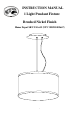
Use and Care Manual


3
10. Wrap the ground wire (#7) under and around the ground screw (#3) which is marked “GND”, and
fasten the ground screw to make sure the ground wire is securely connected.
11. Make the ELECTRICAL CONNECTIONS (Required Supply Circuit: 120V, 60Hz):
a. Connect the White wire (#5) from the fixture to the white wire (#5) (neutral wire) from the Outlet
Box (#1).
b. Connect the Black wire (#6) from the fixture to the Black wire (#6) (live wire) from the Outlet Box
(#1).
c. Connect the ground wire (#7) from the fixture to the ground wire from the Outlet Box (#1).
d. Secure the connections using the Wire Connectors (#2). Wrap the wire connections with electrical
tape to secure the connections.
e. Position the wires back inside the Outlet Box (#1).
Note: If you have electrical questions, consult your local electrical code for approved grounding methods
or obtain the services of a qualified, licensed electrician.
12. Secure the canopy assembly (#10) to the mounting strap (#4) with canopy screws (#9) provided.
13. Check to make sure the canopy is held firmly against the ceiling.
14. Push the adjustable collar (#20) and pull the steel wire rope (#21) up and down when you need to
adjustable the high of fixture as diagram.
15. Rotate the balance bar (#22) to keep the fixture balance when the fixture body unbalance.
16. Installation is complete. Turn on the power at the circuit breaker or fuse box.
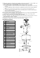
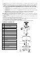
ASSEMBLY DIAGRAM:
1. Outlet Box
2. Wire Connectors
3. Ground Screw
4. Mounting Strap
5. White Wire
6. Black Wire
7. Ground Wire
8. Outlet Box Screw
9. Canopy Screw
10. Canopy assembly
11. Bulb Socket Assembly
12 Shade
13 Socket Ring
14 Light Bulb (sold separately)
15 Thread hole
16 Decorative ring
17 Glass lens
18 Plastic washer
19 Decorative nut
20 Adjustable collar
21 Steel wire rope
22 Balance bar
1
2
7
5
4
10
9
11
12
16
3
13
6
14
8
20
21
22
15